Fixing device and an image forming apparatus including the fixing device

a fixing device and image forming technology, applied in the direction of electrographic process equipment, instruments, optics, etc., can solve the problems of long standby period, hot offset, loss of planarity of the fixing belt, etc., to prevent the deterioration of the image quality of the fixed toner image, prevent the deterioration of the belt and roller, and prevent the effect of deterioration of the image quality

Inactive Publication Date: 2006-03-02
RICOH KK
View PDF18 Cites 19 Cited by
  • Summary
  • Abstract
  • Description
  • Claims
  • Application Information

AI Technical Summary

Benefits of technology

[0017] An object of the present invention is to provide a novel fixing device having a structure in which a period of rise time to a predetermined temperature may be reduced regardless of types of recording media, and damage to a recording medium, belts and rollers may be prevented so as to prevent deterioration in image quality of a fixed toner image.

Problems solved by technology

Such heat rollers may require a long period of rise time at a predetermined temperature, which results in a long standby period.
Some toner particles heated and pressed may attach to the heat member, which may cause a hot offset.
The deformation of the fixing belt along the periphery of the other roller, however, may lose planarity of the fixing belt.
Even though the deformation of the fixing belt may not significantly affect a recording medium having a relatively long length, it may produce a wrinkled surface or a deviated flap of a recording medium having a short length such as an envelope to lose the planarity at the fixing nip portion.
In this case, the leading edge of the stripping finger may rub or scrape the toner image formed on the recording medium and / or may wear or abrade the surface of the fixing belt, which may produce scratches on the recording medium and / or affect durability of the fixing belt due to abrasion.
Toner particles may also be damaged when the fixing belt itself having scratches thereon rubs or scrapes the toner particles in the process of fusing or melting.
This makes it difficult to achieve an elimination of the above-described scratches.
This structure may lose heat dissipated from the fixing belt to the fixing roller when the fixing device is not in operation.
Further, the period of rise time to the predetermined temperature may be longer and / or an equilibrium state of the temperature may be unstable.

Method used


Image

  • Fixing device and an image forming apparatus including the fixing device
  • Fixing device and an image forming apparatus including the fixing device
  • Fixing device and an image forming apparatus including the fixing device

Examples


Embodiment Construction

[0025] In describing preferred embodiments illustrated in the drawings, specific terminology is employed for the sake of clarity. However, the disclosure of this patent specification is not intended to be limited to the specific terminology so selected and it is to be understood that each specific element includes all technical equivalents that operate in a similar manner.

[0026] Referring now to the drawings, wherein like reference numerals designate identical or corresponding parts throughout the several views, preferred embodiments of the present invention are described.

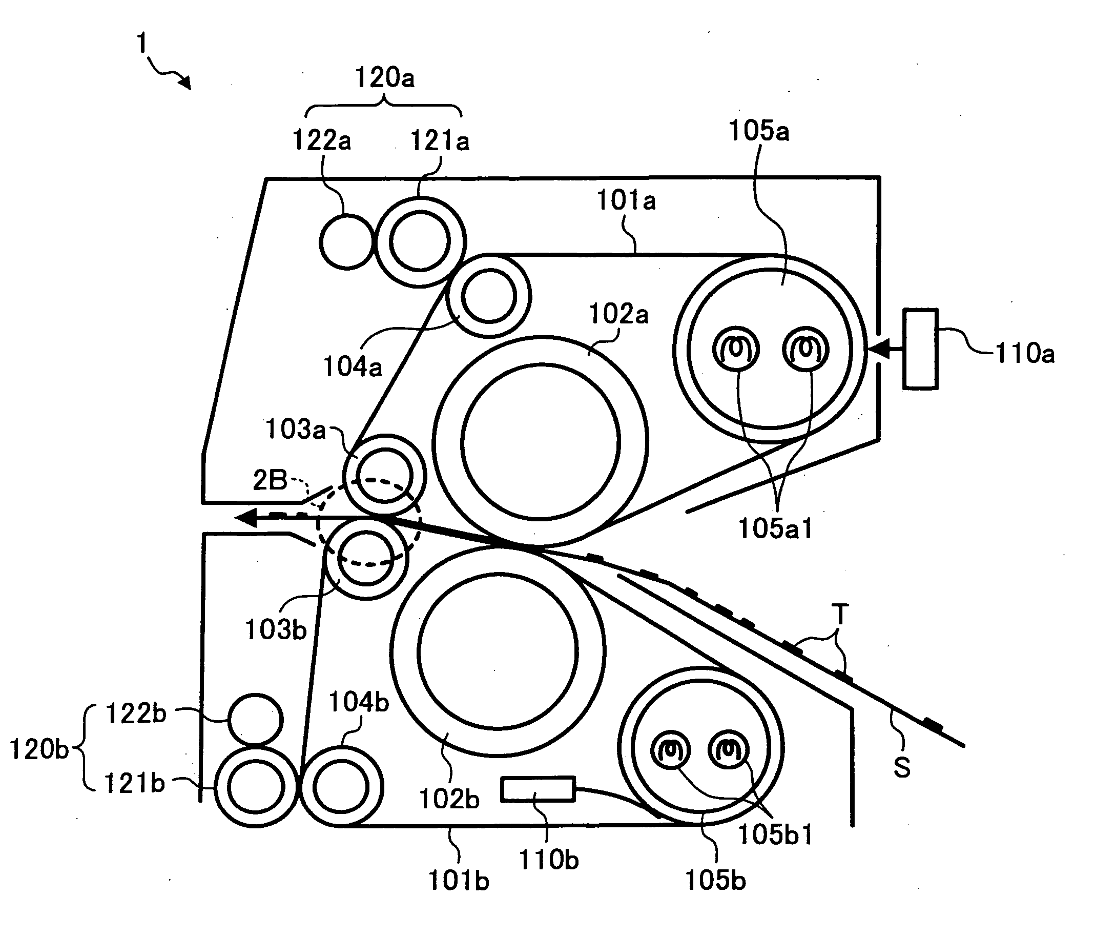
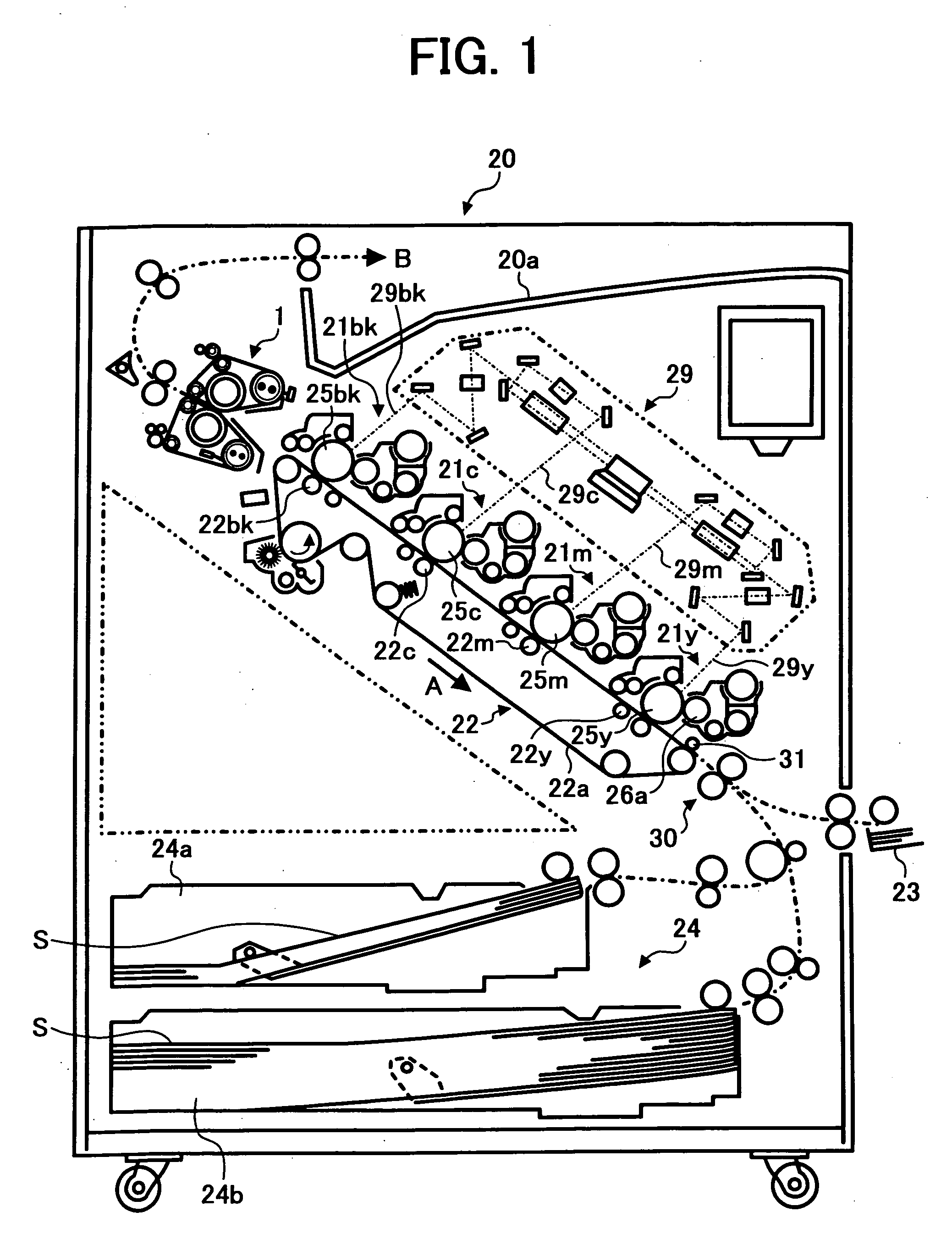
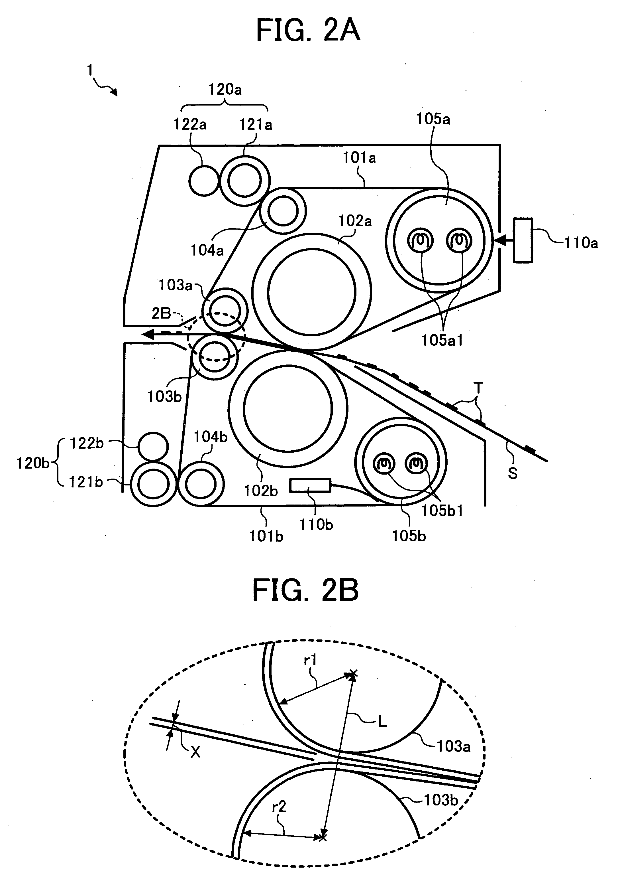
[0027] Referring to FIG. 1, a schematic structure of an image forming apparatus 20 including a fixing device 1 according to an exemplary embodiment of the present invention is described.

[0028] Although the embodiments of the present invention discuss the image forming apparatus 20 serving as a color laser printer in which images are optically written by laser light beams corresponding to image data of different ...


PUM


Abstract

A fixing device for fixing a toner image on a recording medium includes first and second belts rotatably disposed opposite to each other such that the recording medium having the toner image thereon moves therebetween, a fixing roller disposed in contact with an inner surface of the first belt, a pressure roller disposed in contact with an inner surface of the second belt, the fixing and pressure rollers forming a first nip part therebetween, a first supporting member disposed downstream of the fixing roller and held in contact with the inner surface of the first belt, and a second supporting member disposed downstream of the pressure roller and held in contact with the inner surface of the second belt. A second nip part is formed downstream of the first nip portion and upstream of the first and second supporting members facing each other via the first and second belts.

Description

CROSS REFERENCE TO RELATED APPLICATIONS [0001] The present application claims priority to Japanese patent application no. 2004-254649, filed in the Japan Patent Office on Sep. 1, 2004, the disclosure of which is incorporated by reference herein in its entirety. BACKGROUND OF THE INVENTION [0002] 1. Field of the Invention [0003] The present invention relates to a fixing device and an image forming apparatus, and more particularly relates to a fixing device and an image forming apparatus including the fixing device for fixing an image on a recording medium. [0004] 2. Discussion of the Background [0005] In a typical copying or printing process performed by an image forming apparatus, such as a copier, printer, facsimile machine, printing press and the like, an electrostatic latent image formed on an image bearing member or a photoconductive member is developed by conveying one or more developer materials such as toner particles to be transferred to the electrostatic latent image and is...

Claims


Application Information

Patent Timeline
Patent Type & Authority Applications(United States)
IPC IPC(8): G03G15/20
CPCG03G15/2064G03G2215/2016G03G2215/2009G03G15/2053G03G15/206G03G2215/2032
Inventor YAMADA, MASAMICHI
Owner RICOH KK
Why Eureka
Try Eureka