Lens barrel and image pickup unit

a technology of image pickup and lens barrel, which is applied in the field of lens barrel and image pickup unit, can solve the problems of abnormal sound, inconvenience, and deformation of shading characteristics or eclipses, and achieve the effects of improving workability, enhancing adhesive strength of lens, and improving workability in the work of assembling the image pickup uni

Inactive Publication Date: 2012-01-24
SONY CORP
View PDF22 Cites 32 Cited by
  • Summary
  • Abstract
  • Description
  • Claims
  • Application Information

AI Technical Summary

Benefits of technology

[0010]Thus, in order to prevent the lowering of image quality by using a light shielding sheet, a high precision is required of the arrangement position of the light shielding sheet with respect to the lens.
[0044]According to a sixteenth embodiment of the present invention, the tilt of the second lens holder with respect to the first lens holder is set by a thickness of the print pattern formed on the lens, and a tilt of the predetermined lens retained by the second lens holder with respect to the optical axis is adjusted. It is therefore unnecessary to perform the tilt adjustment and the formation of the print pattern as separate pieces of work, and thus workability in the work of assembling the image pickup unit can be improved.

Problems solved by technology

In the case of using a light shielding sheet to prevent the lowering of image quality as in the image pickup device described in Japanese Patent Laid-Open No. 2005-309289, when the positional accuracy of the light shielding sheet with respect to the lens is low, a degradation in shading characteristics or an eclipse occurs.
When a large displacement of the light shielding sheet occurs, an inconvenience may occur in that the light shielding sheet comes into contact with a zoom mechanism, a focus mechanism or the like incorporated in the lens barrel or the image pickup unit at a time of zoom driving or at a time of focus driving, and an abnormal sound is caused by the contact.
However, because the light shielding sheet is disposed at a position different from that of the lens on which rays of light are made incident, there is a high degree of difficulty in ensuring a high positional accuracy of the light shielding sheet with respect to the lens.
As there has been a high demand for smaller size and higher performance as in the case of recent image pickup devices, in particular, it is often difficult to incorporate a light shielding sheet into an optical system of which a high positional accuracy is required with precision in a manufacturing process.

Method used


Image

  • Lens barrel and image pickup unit
  • Lens barrel and image pickup unit
  • Lens barrel and image pickup unit

Examples


first embodiment

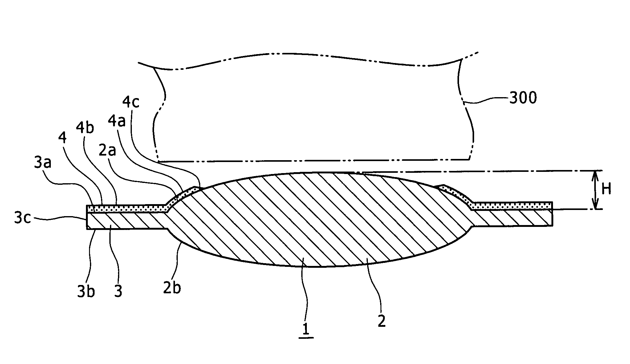
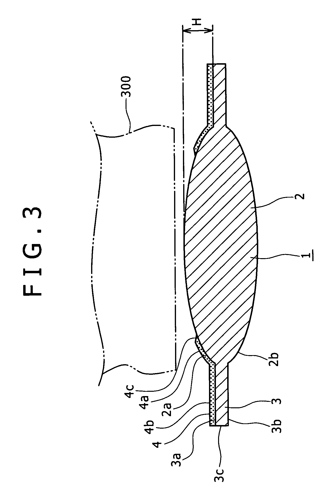
[0027]According to the present invention, there is provided a lens barrel including: a plurality of lenses arranged in a state of being separated from each other in a direction of an optical axis; and a lens retaining body for retaining the lenses; wherein a print pattern that has a light shielding function and is partly in contact with the lens retaining body to adjust an interval between the lenses in the direction of the optical axis is formed on at least one of the plurality of lenses.

[0028]Thus, because the print pattern formed on the lens can exert a light shielding function and adjust the interval between the lenses, it is possible to achieve miniaturization and a reduction in the number of parts in addition to an excellent light shielding property and an improvement in positional accuracy between the lenses.

second embodiment

[0029]According to the present invention, the lens on which the print pattern is formed is formed by a lens section transmitting rays of light and a flange section jutting out from a peripheral section of the lens section. It is thus possible to ensure excellent retainability of the lens by the lens retaining body, and improve the positional accuracy of the lens.

third embodiment

[0030]According to the present invention, the print pattern is formed on a part of the lens section, and the print pattern is formed on at least a part of the flange section. It is thus possible to improve image quality through an improvement in a light shielding property.


PUM


Abstract

Disclosed herein is a lens barrel including: a plurality of lenses arranged in a state of being separated from each other in a direction of an optical axis; and a lens retaining body for retaining the lenses; wherein a print pattern that has a light shielding function and is partly in contact with the lens retaining body to adjust an interval between the lenses in the direction of the optical axis is formed on at least one of the plurality of lenses.

Description

CROSS REFERENCES TO RELATED APPLICATIONS[0001]The present invention contains subject matter related to Japanese Patent Application JP 2008-012575 filed in the Japan Patent Office on Jan. 23, 2008, the entire contents of which being incorporated herein by reference.BACKGROUND OF THE INVENTION[0002]1. Field of the Invention[0003]The present invention relates to a technical field of a lens barrel and an image pickup unit, and particularly to a technical field in which miniaturization and the like are achieved by forming a print pattern that has a light shielding function and which is to adjust an interval between lenses in a direction of an optical axis.[0004]2. Description of the Invention[0005]Various image pickup devices such as video cameras, still cameras and the like have a lens barrel in which a plurality of lenses are arranged in a state of being separated from each other in a direction of an optical axis.[0006]In addition, an image pickup unit referred to as a camera module ha...

Claims


Application Information

Patent Timeline
Patent Type & Authority Patents(United States)
IPC IPC(8): G02B7/02
CPCG02B7/021G02B7/025
Inventor TSUCHIYA, TAKAHIROMIYASAKA, SO
Owner SONY CORP
Why Eureka
Try Eureka