Digital micro-mirror device (DMD) assembly for an optical projection system

a digital micro-mirror and optical projection technology, applied in television systems, cooling/ventilation/heating modifications, kitchen equipment, etc., can solve the problems of difficult to adjust the position of the dmd b>21/b> with these conventional structures, image quality may deteriorate, and the manufacturing process is relatively complicated, so as to achieve easy adjustment of the position of the dmd and improve image quality.

Inactive Publication Date: 2006-10-12
SAMSUNG ELECTRONICS CO LTD
View PDF14 Cites 35 Cited by
  • Summary
  • Abstract
  • Description
  • Claims
  • Application Information

AI Technical Summary

Benefits of technology

[0029] The DMD assembly may further comprise a housing that encloses the DMD module and the DMD holder. The holder may have a plurality of housing connection holes thereon, and wherein the optical holder may further comprise a housing boss having boss holes corresponding to the housing connection holes, so that the housing and the optical holder can be integrally connected with each other. The housing may comprise a plurity of cooling holes. The housing is preferably formed of metal so as to shield electromagnetic interference (EMI). The housing connection holes may be formed larger than the boss holes so that the posi

Problems solved by technology

As a consequence, the manufacturing process is relatively complicated.
Further, adjusting the position of the DMD 21 is difficult w

Method used


Image

  • Digital micro-mirror device (DMD) assembly for an optical projection system
  • Digital micro-mirror device (DMD) assembly for an optical projection system
  • Digital micro-mirror device (DMD) assembly for an optical projection system

Examples


Embodiment Construction

[0044] The matters defined in the description such as a detailed construction and elements are provided to assist in a comprehensive understanding of the embodiments of the invention. Accordingly, those of ordinary skill in the art will recognize that various changes and modifications of the embodiments described herein can be made without departing from the scope and spirit of the invention. Also, descriptions of well-known functions and constructions are omitted for clarity and conciseness.

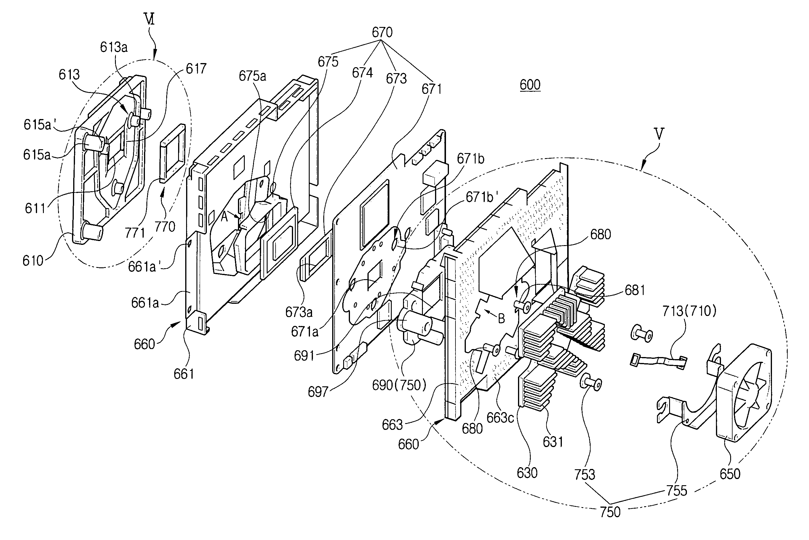
[0045]FIG. 3 is a perspective view showing the structure of an optical engine with a digital micro-mirror device (DMD) assembly according to an exemplary embodiment of the present invention. Referring to FIG. 3, an optical engine 500 comprises a base 501, a lighting unit 510, a DMD assembly 600, and a projection lens unit 530. A light projected from the lighting unit 510 is reflected from a DMD of the DMD assembly 530 toward the projection lens unit 530. The DMD will be described in detail late...


PUM


Abstract

A digital micro-mirror assembly for an optical projection system includes a DMD module with a control board. The control board is provided with a first fixing member, and a DMD is mounted on one side of the control board. A DMD holder resiliently supports a perimeter of the DMD, and an optical holder is provided with a second fixing member to support the DMD module. A fastening member is engaged with the first and the second fixing members to integrally connect the DMD module and the optical holder.

Description

CROSS-REFERENCE TO RELATED APPLICATIONS [0001] This application claims the benefit under 35 U.S.C. §119(a) of Korean Patent Application No. 2005-29379, filed Apr. 8, 2005, the entire contents of which are hereby incorporated by reference. BACKGROUND OF THE INVENTION [0002] 1. Field of the Invention [0003] The present invention relates to an optical projection system. More particularly, the present invention relates to a digital micro-mirror device (DMD) assembly for an optical projection system that has an improved structure. [0004] 2. Description of the Related Art [0005] Optical projection systems are used to project a small image onto a relatively large, wide screen using an optical device. Optical projection systems can be generally divided into three types of systems: cathode ray tube (CRT) projection systems, a liquid crystal display (LCD) projection systems, and digital light processing (DLP) projection systems. [0006] The CRT projection system is the oldest type of system. I...

Claims


Application Information

Patent Timeline
IPC IPC(8): H05K7/20
CPCH04N5/7458A47J45/06A47J43/28
Inventor KANG, BYUNG-JOJANG, KYOUNG-CHOULLEE, HEONG-SEOG
Owner SAMSUNG ELECTRONICS CO LTD
Why Eureka
Try Eureka