Projection system for EUV lithography

a projection system and lithography technology, applied in the field of microlithography objectives, can solve the problems of reducing the throughput of the entire projection apparatus, the system is very long (3000 mm), and the examples are not well suited to contemporary lithography at extreme ultraviolet wavelengths, etc., to achieve the effect of efficient masking of undesired light, easy manufacturing, and convenient mechanical achievemen

Inactive Publication Date: 2006-12-19
CARL ZEISS SMT GMBH
View PDF41 Cites 32 Cited by
  • Summary
  • Abstract
  • Description
  • Claims
  • Application Information

AI Technical Summary

Benefits of technology

[0033]The objective can be used not only in the EUV, but also at other wavelengths, without deviating from the scope of the invention. In any respect, however, to avoid degradation of image quality, especially degradation due to central shading, the mirrors of the projection objectives should be arranged so that the light path of the bundle of light rays traveling from the object plane to the image plane is obscuration-free. Furthermore, to provide easy mounting and adjusting of the system, the physical mirror surfaces have a rotational symmetry to a principal axis (PA). Moreover, to have a compact design with an accessible aperture and to establish an obscuration-free light path of the bundle of light rays traveling from the object plane to the image plane, the projection objective device is designed in such a way that an intermediate image of the object situated in the object plane is formed after the fourth mirror. In such systems, it is possible that the aperture stop is situated in the front, low-aperture objective part, with a pupil plane conjugated to the aperture stop imaged in the focal plane of the last mirror. Such a system ensures telecentricity in the image plane.
[0037]In such a system, the angles of incidence on the physical mirror surfaces in the front part of the objective are reduced.
[0038]An aperture stop which physically lies between the second mirror, S2, and the first mirror, S1, must be formed at least partially as a narrow ring in order to avoid clipping of light moving from S1 to S2. In such a design, there is a danger that undesirable direct light or light reflected on S1 and S2, will pass outside the aperture ring and reach the image plane and thus the wafer. However, if the aperture stop is placed in the light path between the second and third mirror and physically close to the first mirror (which can be easily achieved mechanically), an efficient masking of this undesired light is possible. The aperture stop can be designed both as an opening in the first mirror or an opening which is arranged behind the first mirror.
[0039]In another embodiment of the invention, the aperture stop is arranged on or near the second mirror. Arrangement of the aperture on a mirror has the advantage that it is easier to manufacture.
[0041]In order to be able to make the necessary corrections of imaging errors in the six-mirror systems, in a preferred embodiment, all six mirrors are designed to be aspherical. However, an alternative embodiment whereby at most five mirrors are aspherical can simplify the manufacturing, because it is then possible to design one mirror, preferably the largest mirror, i.e., the quaternary mirror, in the form of a spherical mirror. Moreover, it is preferred that the second to sixth mirror be in a concave-convex-concave-convex-concave sequence.

Problems solved by technology

This reduction in ring field width results directly in reduced throughput of the entire projection apparatus.
While minimizing the number of reflections has several advantages particular to EUV lithography, an odd number of reflections create a problem in that new stage technology would need to be developed to enable unlimited parallel scanning.
While the embodiments disclosed in the '240 patent appear to achieve their stated purpose, these examples are not well suited for contemporary lithography at extreme ultraviolet wavelengths.
First, the systems are very long (˜3000 mm) and would suffer mechanical stability problems.
Second, the embodiments do not support telecentric imaging at the wafer which is desired for modern semiconductor lithography printing systems.
Lastly, the numerical aperture is rather small (˜0.05) leaving the systems unable to address 30 nm design rules.
While these systems were designed for DUV lithography and are fine for that purpose, these embodiments make very poor EUV projection systems.
Even after the numerical aperture is reduced from 0.50 to 0.25, the incidence angles of the ray bundles are very large at every mirror including the mask, making the system incompatible with either Mo / Si or Mo / Be multilayers.
While the prior art projection optical systems have proven adequate for many applications, they're not without design compromises that may not provide an optimum solution in all applications.

Method used


Image

  • Projection system for EUV lithography
  • Projection system for EUV lithography
  • Projection system for EUV lithography

Examples


embodiment

Preferred Embodiment

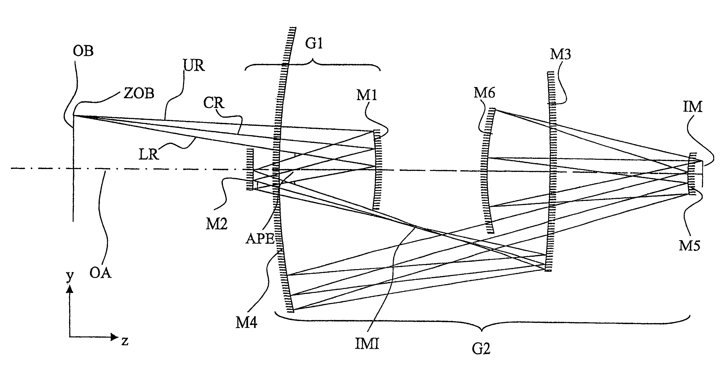
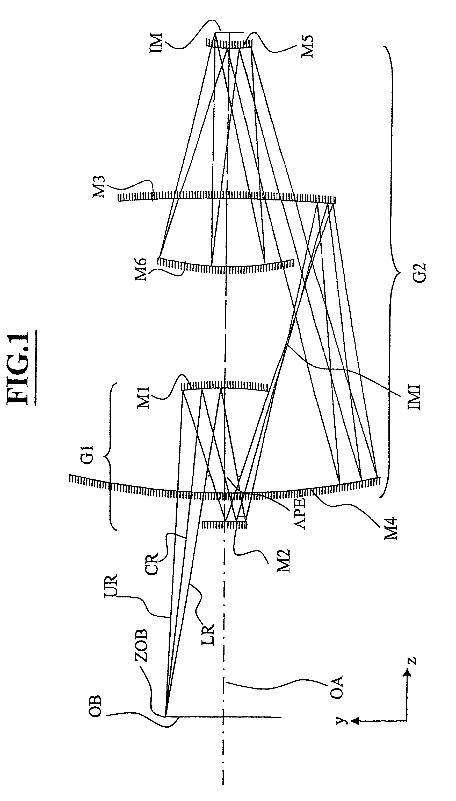
[0070]FIG. 1 schematically illustrates a first preferred embodiment, and, taking in conjunction with Table 1 and Table 2, provides an illustrative, exemplary description of this embodiment. Light impinges on an object OB, e.g. a reflective mask or a reticle, from an illumination source and is directed to concave mirror M1 after which it reflects from the mirror and passes through a physically accessible aperture stop APE that is located between mirror M1 and mirror M2. This aperture stop APE is a substantial distance from the first concave mirror M1 and, likewise, this aperture stop APE is located a substantial distance from convex mirror M2. After the illumination reflects off convex mirror M2, the light comes to a focus at an intermediate image IMI that is located in close proximity to concave mirror M3. From mirror M3 the illumination is directed toward concave mirror M4 where the light is nearly collimated and directed toward convex mirror M5. Upon reflection...


PUM

PropertyMeasurementUnit
incidence angleaaaaaaaaaa
physical distanceaaaaaaaaaa
incidence angleaaaaaaaaaa

Abstract

An EUV optical projection system includes at least six mirrors (M1, M2, M3, M4, M5, M6) for imaging an object (OB) to an image (IM). At least one mirror pair is preferably configured as an at least phase compensating mirror pair. The system is preferably configured to form an intermediate image (IMI) along an optical path from the object (OB) to the image (IM) between a second mirror (M2) and a third mirror (M3), such that a first mirror (M1) and the second mirror (M2) form a first optical group (G1) and the third mirror (M3), a fourth mirror (M4), a fifth mirror (M5) and a sixth mirror (M6) form a second optical group (G1). The system also preferably includes an aperture stop (APE) located along the optical path from the object (OB) to the image (IM) between the first mirror (M1) and the second mirror (M2). The second mirror (M2) is preferably convex, and the third mirror (M3) is preferably concave. The system preferably forms an image (IM) with a numerical aperture greater than 0.18.

Description

CROSS-REFERENCE TO RELATED APPLICATIONS[0001]The present application is a continuation of International Application No. PCT / EP02 / 00030 and a continuation in part of U.S. patent application Ser. No. 10 / 004,674. The PCT / EP02 / 00030 application was filed Jan. 4, 2002, and claims priority of U.S. Provisional Patent Application Ser. No. 60 / 260,799, which was filed Jan. 9, 2001. The Ser. No. 10 / 004,674 application was filed Dec. 3, 2001 which is now U.S. Pat. No. 6,600,552 and is a continuation-in-part of U.S. patent application Ser. No. 09 / 503,640. The Ser. No. 09 / 503,640 application was filed Feb. 14, 2000 and issued as U.S. Pat. No. 6,353,470. The present application is also claiming priority of (a) German Patent Application No. 19906001 filed Feb. 15, 1999, and (b) German Patent Application No. 199 48 240 filed Oct. 7, 1999.BACKGROUND OF THE INVENTION[0002]1. Field of the Invention[0003]The present invention relates to a microlithography objective, a projection exposure apparatus conta...

Claims


Application Information

Patent Timeline
Patent Type & Authority Patents(United States)
IPC IPC(8): G03B27/54G02B5/10G03B27/72G02B17/06G03F7/20
CPCG02B17/0652G02B17/0657G03F7/70233G03F7/70275
Inventor HUDYMA, RUSSELLMANN, HANS-JURGENDINGER, UDO
Owner CARL ZEISS SMT GMBH
Why Eureka
Try Eureka