
Electronic roll indexing compensation in a drilling system and method
a directional drilling and compensation technology, applied in the direction of directional drilling, surveying, borehole/well accessories, etc., can solve the problems of difficult mechanical indexing arrangement of a transmitter, prone to complex mechanical indexing arrangement, and in the presence of a bent sub or mechanically similar arrangemen
- Summary
- Abstract
- Description
- Claims
- Application Information
AI Technical Summary
Benefits of technology
Problems solved by technology
Method used
Image

Examples
Embodiment Construction
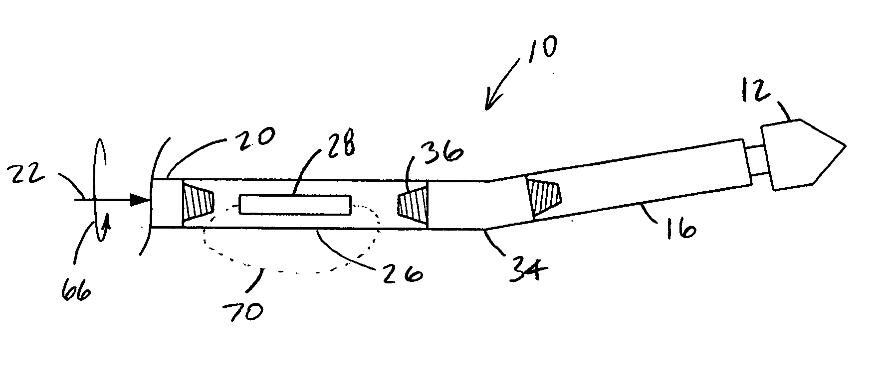
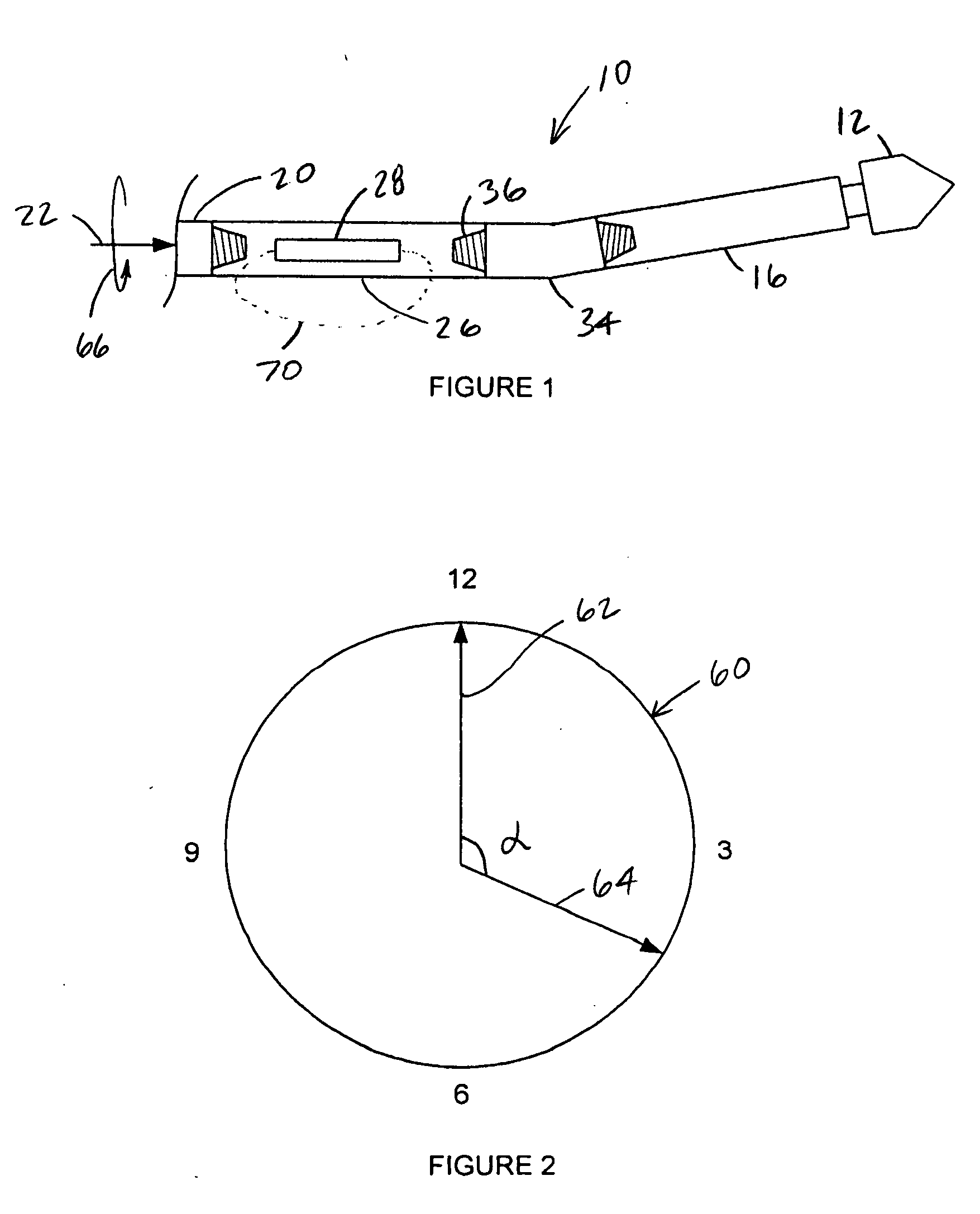
[0019] Turning now to the figures, in which like reference numbers are used to refer to like items whenever possible throughout the various figures, attention is immediately directed to FIG. 1 which illustrates a downhole drilling arrangement produced in accordance with the present invention and generally indicated by the reference numeral 10. It is noted that the figures are diagrammatic for purposes of enhancing the reader's understanding. Further, the drawings are not to scale for purposes of better illustrating features that are of interest. Moreover, terminology such as, for example, behind / ahead, vertical / horizontal, left / right and up / down is used for descriptive purposes only and is in no way intended as being limiting.
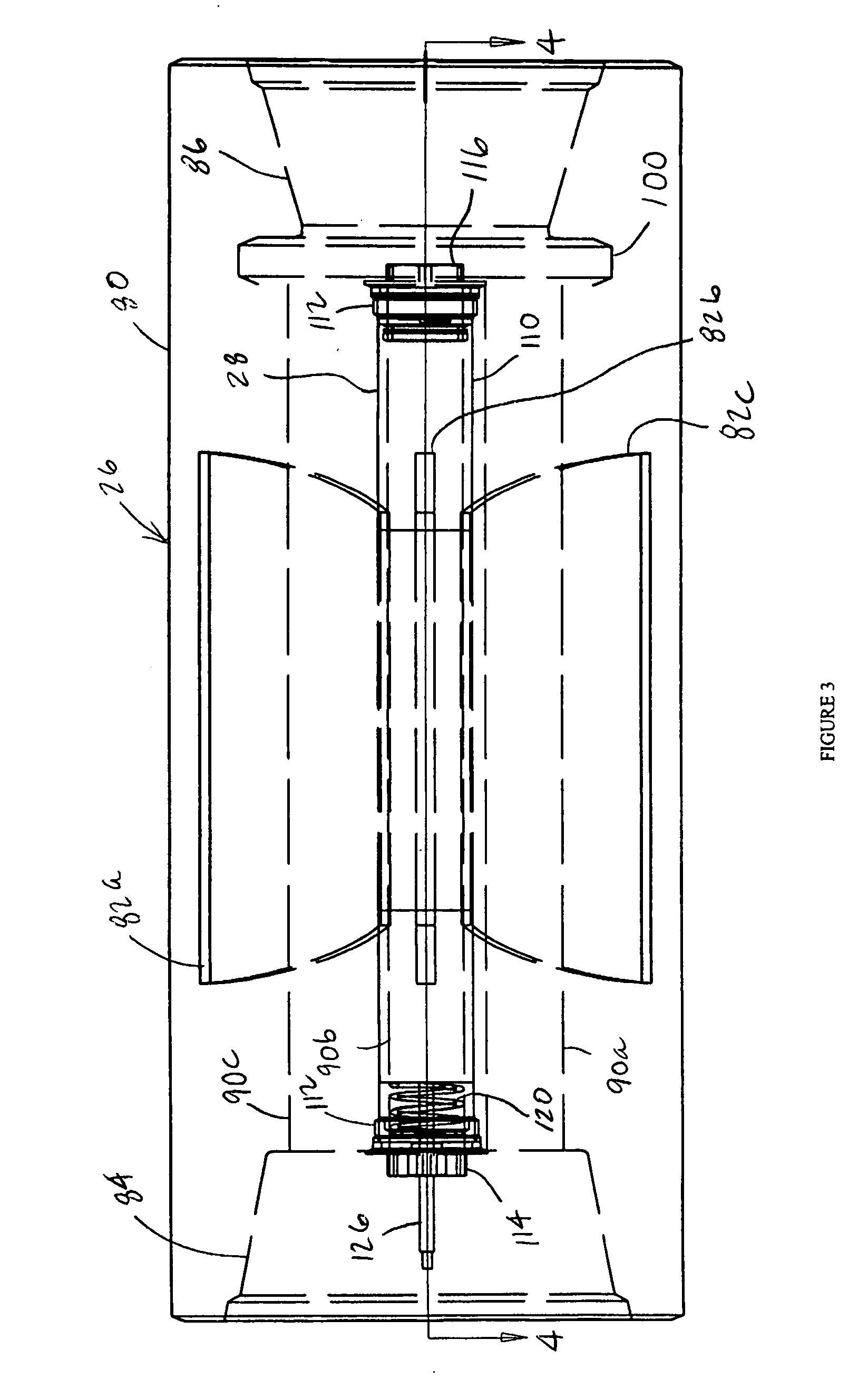
[0020] Still referring to FIG. 1, arrangement 10 includes a drill bit 12 which is rotated, for example, by a mud motor (not shown) contained by a mud motor section 16. It is noted that such mud motors are well-known to those having ordinary skill in the art. T...
PUM
 Abstract
Description
Claims
Application Information