Electronic roll indexing compensation in a drilling system and method

a directional drilling and compensation technology, applied in the direction of directional drilling, surveying, borehole/well accessories, etc., can solve the problems of difficult mechanical indexing arrangement of a transmitter, prone to complex mechanical indexing arrangement, and in the presence of a bent sub or mechanically similar arrangemen

Active Publication Date: 2007-07-03
MERLIN TECH INC
View PDF13 Cites 0 Cited by
  • Summary
  • Abstract
  • Description
  • Claims
  • Application Information

AI Technical Summary

Benefits of technology

[0006]As will be discussed in more detail hereinafter, there is disclosed herein an apparatus and associated method used in a system for forming a borehole including a drill string which is made up of a series of elongated sections that is connected to a leading arrangement having a steering configuration that is responsive to a roll position thereof, which roll position is controlled using the drill string. In one aspect of the present invention, an assembly is provided that is configured for sensing a roll orientation thereof, referenced to a roll indexing orientation that is defined by the assembly, so as to produce a roll output signal and for transmitting the roll output signal in a predetermined way. A housing is configured to support the assembly in relation to the drill string behind the leading arrangement in fixed rotational communication with the leading arrangement such that the roll indexing orientation is in a fixed, but arbitrary angular offset with respect to the roll position of the leading arrangement. With the assembly supported in the housing, the roll position of the steering configuration is oriented in a predetermined way. The roll output signal is received, with the steering configuration of the leading arrangement oriented in the predetermined way, for use in identifying a value of the fixed angular offset. The value of the fixed angular offset can then be saved.
[0007]In another aspect of the present invention, in which an apparatus and associated method are used in a system for forming a borehole including a drill string which is made up of a series of elongated sections that is connected to a leading arrangement having a steering configuration that is responsive to a roll position thereof, which roll position is controlled using the drill string, an assembly is configured for sensing a roll orientation thereof, referenced to a roll indexing orientation that is defined by the assembly, so as to produce a roll output signal and for transmitting the roll ouput signal in a predetermined way. A housing is configured to support the assembly for fixedly co-rotating the assembly with the leading arrangement such that the roll indexing orientation is in a fixed angular offset with respect to any given roll position of the leading arrangement, which fixed angular offset is arbitrarily established between the housing and the leading arrangement. A roll compensation value is established that is a constant in view of the fixed angular offset. The roll compensation value can then be saved.

Problems solved by technology

This result generally obtains since the mud motor is a relatively complex and long assembly having a central rotating drive shaft which rotates the drill bit.
A mechanical indexing arrangement for a transmitter is therefore difficult to provide since the transmitter is generally located in the drill string behind the mud motor and the bent sub.
Accordingly, mechanical indexing arrangements, in the presence of a bent sub or mechanically similar arrangement, tend to be quite complex in order to appropriately index the transmitter zero roll orientation to the steering direction of the bent sub.

Method used


Image

  • Electronic roll indexing compensation in a drilling system and method
  • Electronic roll indexing compensation in a drilling system and method
  • Electronic roll indexing compensation in a drilling system and method

Examples


Embodiment Construction

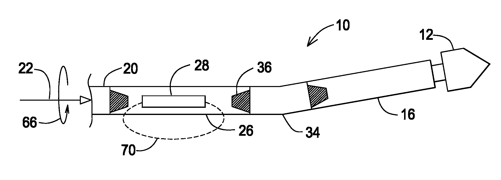
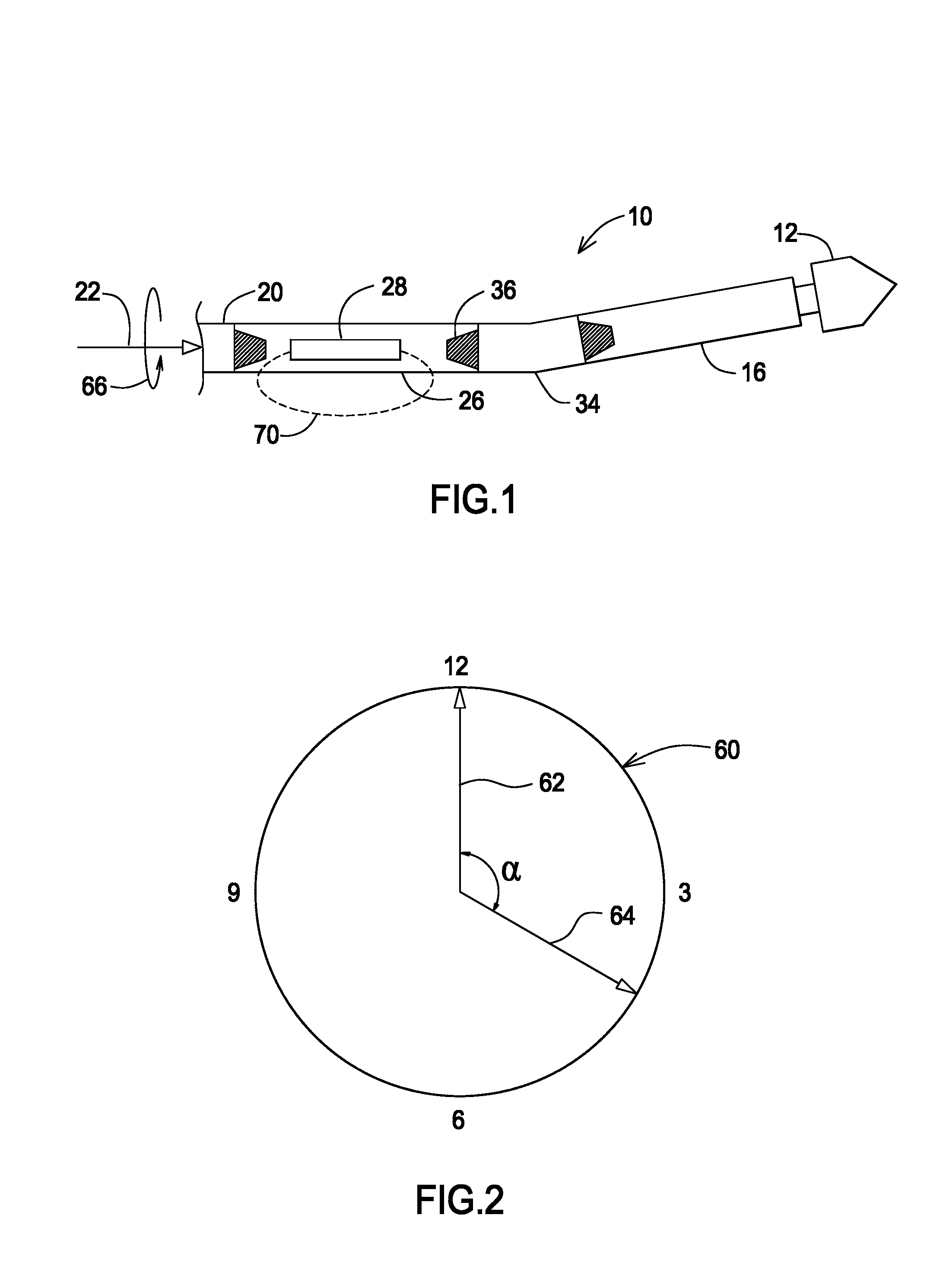
[0019]Turning now to the figures, in which like reference numbers are used to refer to like items whenever possible throughout the various figures, attention is immediately directed to FIG. 1 which illustrates a downhole drilling arrangement produced in accordance with the present invention and generally indicated by the reference numeral 10. It is noted that the figures are diagrammatic for purposes of enhancing the reader's understanding. Further, the drawings are not to scale for purposes of better illustrating features that are of interest. Moreover, terminology such as, for example, behind / ahead, vertical / horizontal, left / right and up / down is used for descriptive purposes only and is in no way intended as being limiting.

[0020]Still referring to FIG. 1, arrangement 10 includes a drill bit 12 which is rotated, for example, by a mud motor (not shown) contained by a mud motor section 16. It is noted that such mud motors are well-known to those having ordinary skill in the art. The ...


PUM


Abstract

An assembly is configured for sensing its roll orientation, referenced to a roll indexing orientation that is defined by the assembly, so as to produce a roll output signal and for transmitting the roll output signal in a predetermined way. A housing is configured to support the assembly for fixedly co-rotating the assembly with the leading arrangement such that the roll indexing orientation is in a fixed angular offset with respect to any given roll position of the leading arrangement, which fixed angular offset is arbitrarily established between the housing and the leading arrangement. A roll compensation value is established that is a constant in view of the fixed angular offset. In one feature, the roll output signal is received with the steering configuration of the leading arrangement oriented in a particular way, for identifying a corresponding value of the fixed angular offset.

Description

BACKGROUND OF THE INVENTION[0001]The present invention is related generally to the field of directional drilling and, more particularly, to electronic roll indexing compensation in a directional drilling system and method.[0002]Drilling systems generally use a drill string which extends from a drill rig, positioned at the surface of the ground, to an inground boring tool or downhole arrangement which is connected to a foremost end of the drill string. The specific configuration of the downhole arrangement may vary substantially, depending on the specific type of drilling operation that is being performed. Generally, however, directional drilling utilizes some form of downhole assembly which allows for steering the drill head in a controlled manner. In one configuration, the downhole arrangement includes a drill head having an asymmetric face. So long as the drill string is rotated continuously, a straight borehole is formed, assuming uniform soil conditions. In order to steer the dr...

Claims


Application Information

Patent Timeline
Patent Type & Authority Patents(United States)
IPC IPC(8): E21B47/02E21B7/06
CPCE21B47/024
Inventor CHAU, ALBERT W.TIAN, HONGGI
Owner MERLIN TECH INC
Why Eureka
Try Eureka