Debris flow retaining apparatus

a flow retaining and debris technology, applied in shaft equipment, shaft lining, artificial islands, etc., can solve the problems of large damage, incur devastating damage or disaster, and require a lot of time to plan and implement, and achieve the effect of reducing damag

Inactive Publication Date: 2006-03-16
HWANG JYH YEONG
View PDF3 Cites 10 Cited by
  • Summary
  • Abstract
  • Description
  • Claims
  • Application Information

AI Technical Summary

Benefits of technology

[0004] In order to solve the aforesaid disadvantages, the primary object of the present invention is to provide a retaining unit that has a hard structure to stop the debris flow and a buffer unit behind the retaining unit that has a flexible buffering capability. The buffer unit includes an air mattress located between the ground surface and the retaining unit and an air compressor to inflate the air mattress. When debris flow occurs, the air compressor inflates the air mattress to raise the retaining unit. The air mattress provides a flexible buffering power to absorb the impact stress generated by the impact of the debris flow so that immediate crumpling of the retaining wall happened to the conventional techniques may be prevented to reduce the damage.

Problems solved by technology

It could cause great damages.
It is a natural disaster happened mostly in mountainous areas, especially the slope lands that are geographically unstable and where the rocks are broken down to gravel of varying sizes under weathering.
Once a torrential rain occurs, and the water cannot be channeled and discharged efficiently, the debris and water are mixed up and slide down of the slope lands under gravity force and form a debris flow that could incur devastating damages or disasters.
However, all these measures require a lot of time to plan and implement.
But practical experiences indicate that the retaining wall is not effective.
As the debris flow slides downwards under the gravity force, and often contains rocks and stones weighted in tons, the impact is huge.
The retaining wall is prone to crumple under the strong impact stress and becomes ineffective.

Method used


Image

  • Debris flow retaining apparatus
  • Debris flow retaining apparatus
  • Debris flow retaining apparatus

Examples


Embodiment Construction

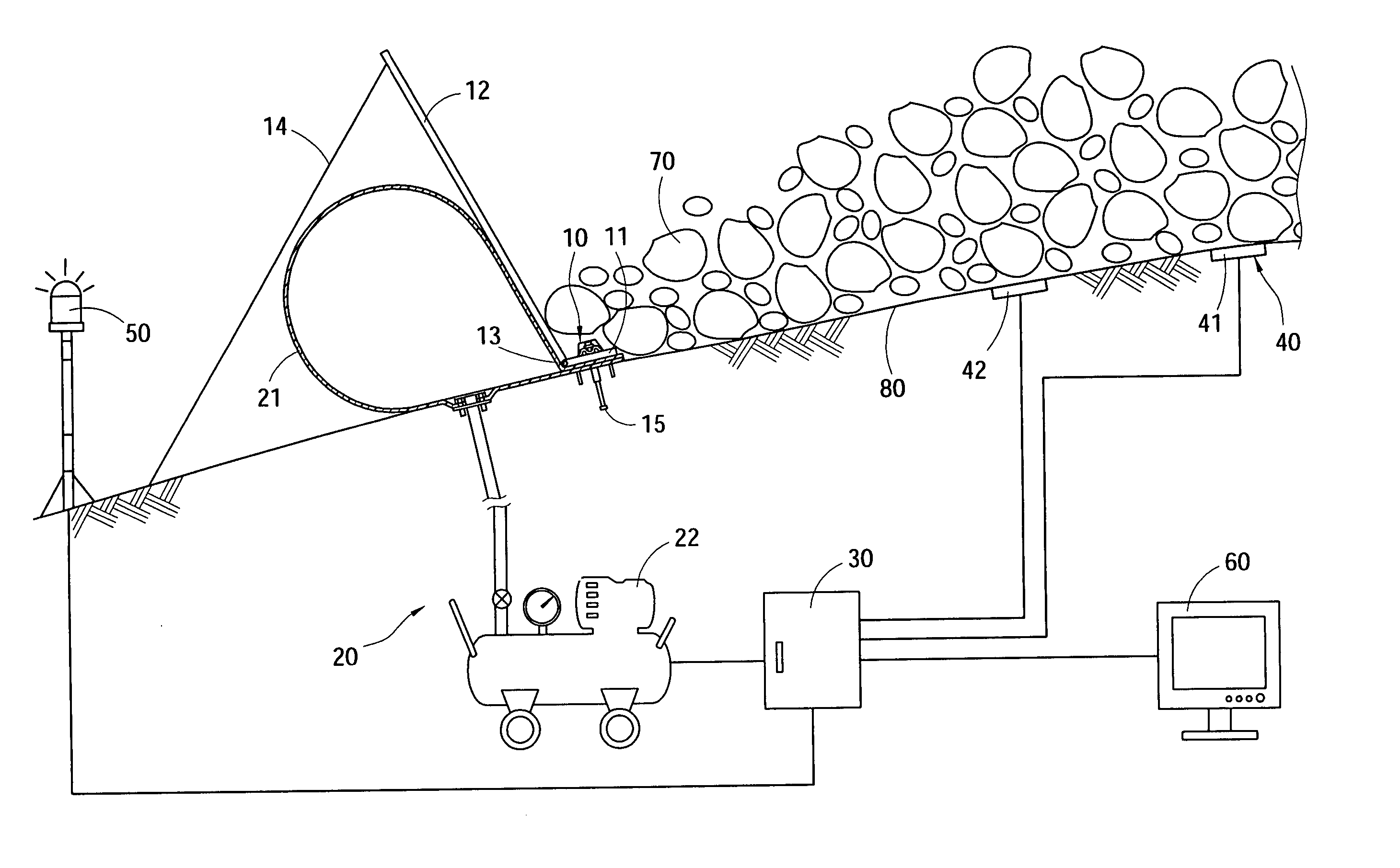
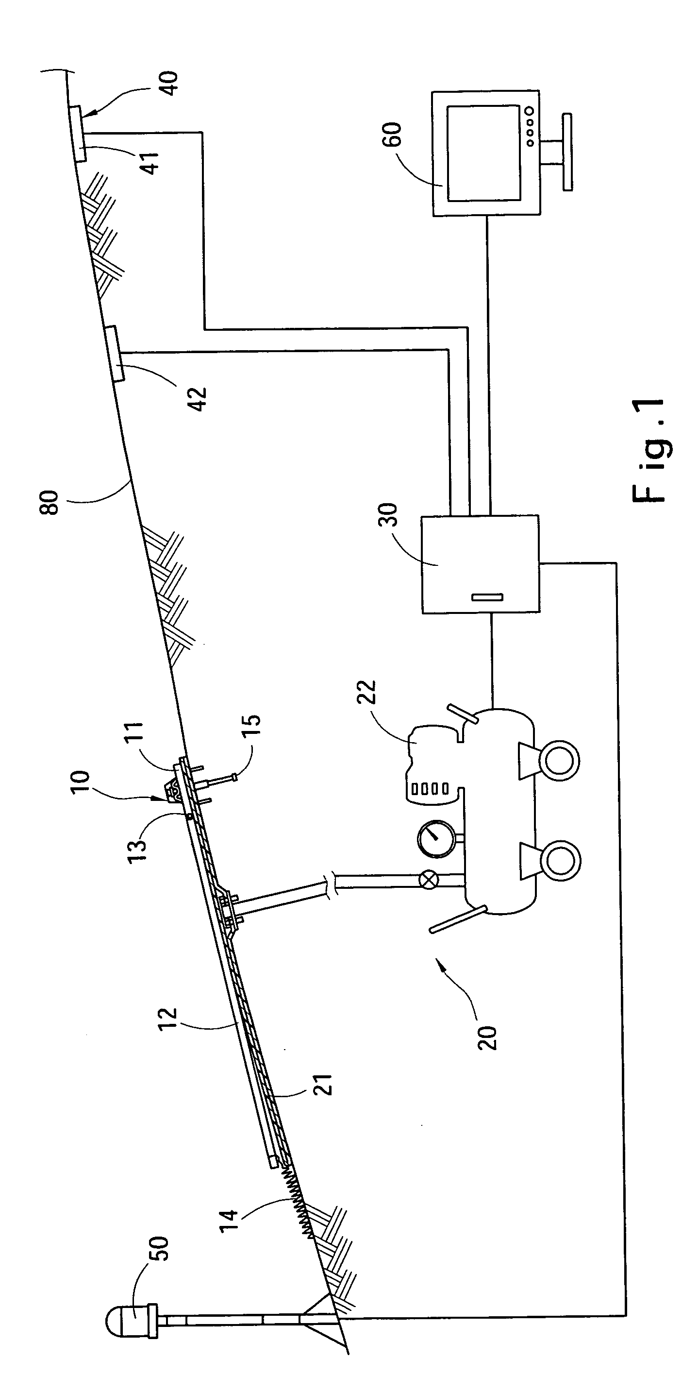
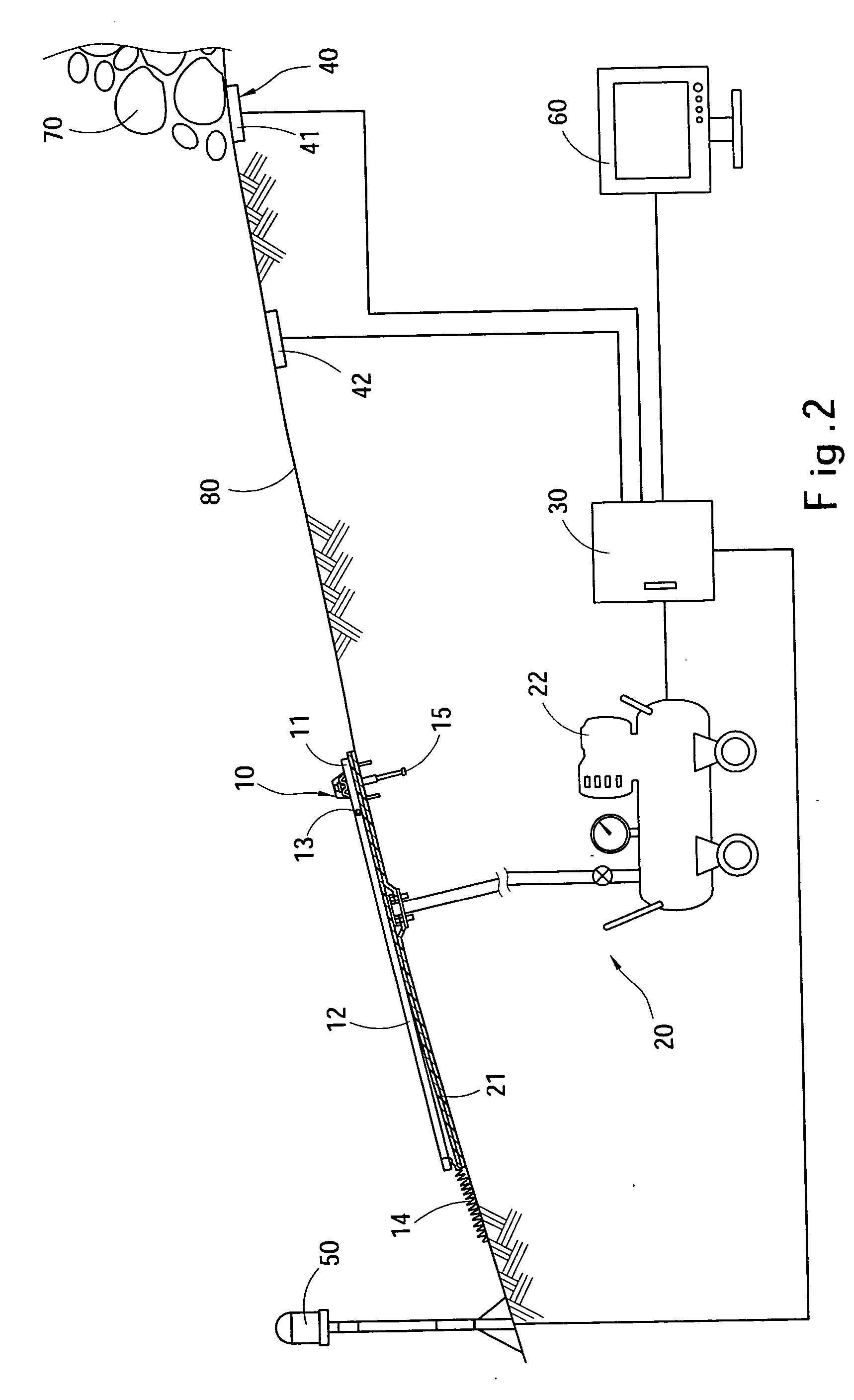
[0012] Please referring to FIG. 1, the retaining apparatus according to the present invention aims to be installed in an active area of a debris flow 70 to provide buffering effect. The retaining apparatus includes a retaining unit 10 mounted onto a ground surface 80 that is movable upwards and downwards relative to the ground surface 80 and a buffer unit 20 which includes an air mattress 21 located between the ground surface 80 and the retaining unit 10, and an air compressor 22 to inflate the air mattress 21.

[0013] The retaining unit 10 includes an anchor board 11 fastened to the ground surface 80 through a fastening member 15 and an elevating board 12 pivotally coupled with the anchor board 11 through a shaft 13. There is a stopper 14 which may be a rope to bridge the elevating board 12 and the ground surface 80 to prevent the elevating board 12 from turning excessively and overturning. The anchor member 15 is formed like an earth spike. The air compressor 22 of the buffer unit ...


PUM


Abstract

A debris flow retaining apparatus located in a debris flow active area to provide buffering retention. It includes a retaining unit anchored on a ground surface movable up and down relative to the ground surface and a buffer unit which has an air mattress located between the ground surface and the retaining unit and an air compressor to inflate the air mattress. When a debris flow occurs, the air compressor inflates the air mattress to raise the retaining unit and absorb the impact stress resulting from the impact of the debris flow to prevent the retaining unit from immediate crumpling and reduce damages caused by the debris flow.

Description

FIELD OF THE INVENTION [0001] The present invention relates to a debris flow retaining apparatus and particularly to an apparatus that has a retaining unit cushioned by a buffering air mattress to absorb and allay the stress caused by the strong impact of debris flow to prevent immediate crumpling of the retaining unit to reduce damages. BACKGROUND OF THE INVENTION [0002] Debris flow (also called mud slide) is a moving slurry with debris mixing up with a great amount of water in which more than half of the contents are solid substances. The solid substances contain gravel greater than sands, and stones and rock debris. It usually is caused by landslide. When there is also a heavy rainfall, the water mixes up with the rock debris and soils to become slurry, and slide or flow along the ground surface of slope lands. It could cause great damages. It is a natural disaster happened mostly in mountainous areas, especially the slope lands that are geographically unstable and where the rock...

Claims


Application Information

Patent Timeline
Patent Type & Authority Applications(United States)
IPC IPC(8): E21D5/00E02D5/00
CPCE02D17/20E01F7/045
Inventor HWANG, JYH-YEONG
Owner HWANG JYH YEONG
Why Eureka
Try Eureka