Image forming method and apparatus, and a recording medium storing a program for performing an image forming method

a technology of image forming and forming methods, applied in the field of image forming methods and apparatuses, can solve the problems of increasing the cost of mechanical parts and a control system of the apparatus, further increasing the cost, and it is difficult to arrange the energy irradiation apparatuses in a completely linear form

Active Publication Date: 2006-04-20
RICOH KK
View PDF3 Cites 13 Cited by
  • Summary
  • Abstract
  • Description
  • Claims
  • Application Information

AI Technical Summary

Benefits of technology

[0023] It is a general object of the present invention to provide an improved and use...

Problems solved by technology

According to the apparatus of the Patent Document 1, costs of mechanical parts and a control system of the apparatus are increased since independently controllable moving means must be provided to a plurality of recording heads.
Additionally, the cost is further increased if a number of the heads is large.
However, it is difficult to arrange the energy irradiation apparatuses completely linear form.
That is, the energy fluxes cannot be arranged in a linear form accurately due to an error when fixing the energy irradiation devices on the table, an error in positions at which the energy fluxes are converged, an error in positions where energy is generated, etc.
Due to the above-mentioned errors, an image recorded on the printing plate material cannot be one in which the image original data is reflected.
This is because there is a misalignment generated between the positions of the image original data shared by the energy irradiation devices and positions actually recorded on the printing plate material.
The printing plate material has an expandability of a certain level, and an environmental condition such as temperature or humidity and image writing energy may be a cause of deformation.
Accordingly, a misalignment may be generated due to an error in positions of mounting the energy irradiation devices.
If an attempt is made to cause a misalign...

Method used


Image

  • Image forming method and apparatus, and a recording medium storing a program for performing an image forming method
  • Image forming method and apparatus, and a recording medium storing a program for performing an image forming method
  • Image forming method and apparatus, and a recording medium storing a program for performing an image forming method

Examples


second embodiment

[0167] A description will now be given, with reference to FIGS. 28 through 31, of a second embodiment of the present invention.

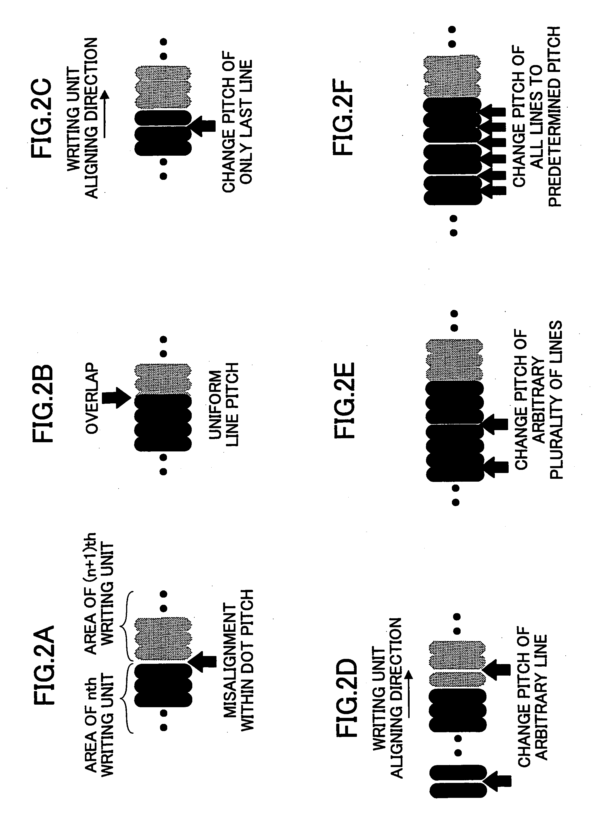
[0168] In an image forming method according to the present embodiment, an image is formed based on divided image data which is obtained by dividing original image data into pieces of image data corresponding to a plurality of lines. The divided images are written on a surface of a recording medium in accordance with the divided image data so as to form an image while a shift of each line in the divided image data is arbitrarily varied.

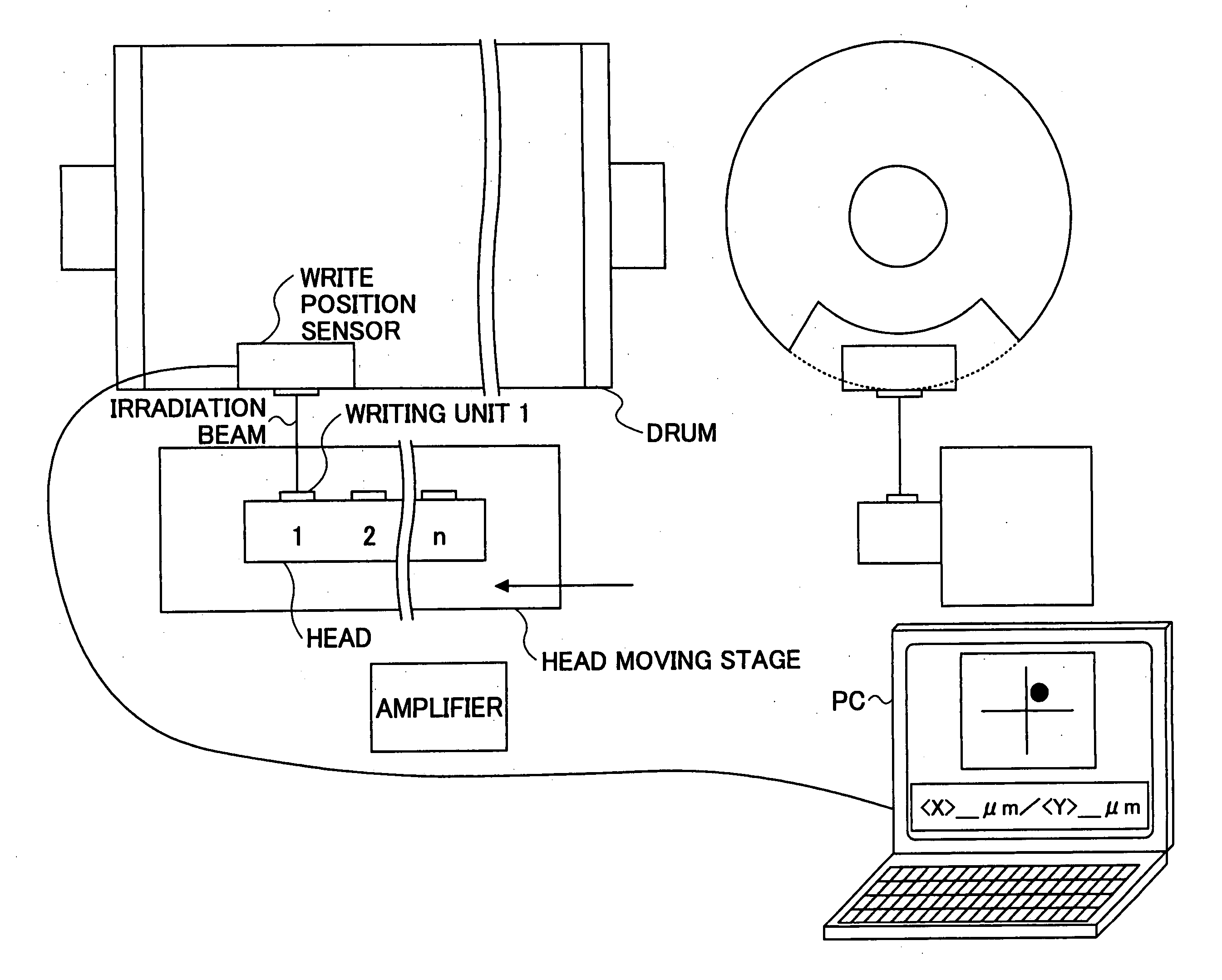
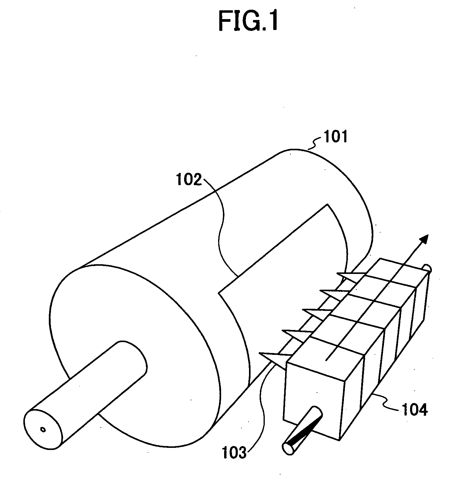
[0169]FIG. 28 is an illustration of a structure of an image forming apparatus according to the second embodiment of the present invention. In FIG. 28, an image forming part comprises a drum 11 rotatable by a power source (not shown in the figure) and a plurality of energy irradiation devices 14 which irradiate energy fluxes onto a printing plate attached to an outer surface or an inner surface of the drum 11.

[0170] A drum di...

third embodiment

[0195] A description will now be given, with reference to FIGS. 32 through 41, of a third embodiment of the present invention.

[0196] An image forming or recording apparatus performing an image processing method according to the third embodiment of the present invention has the same structure as the image forming apparatus according to the second embodiment as shown in FIG. 28, and descriptions thereof will be omitted.

[0197] A description will be given of a process of adding image recording apparatus information to image data to be sent to the image recording or forming apparatus using the image processing method according to the present embodiment. Hereinafter, the image recording or forming apparatus may be referred to as an image recording apparatus.

[0198] The image recording apparatus changes a scan position when recording an image in accordance with scan position information. Here, the scan position information contains information representing irregularity in a formed image ...


PUM


Abstract

An image forming method is performed by an image forming apparatus having a head mounting a plurality of writing units that form an image on a recording medium. The writing units are aligned in a sub-scanning direction perpendicular to a main-scanning direction. A part of the image is formed on the recording medium by the writing units, the part of the image forming a line extending in the main-scanning direction. The step of forming a part of the image is repeated while shifting the writing units in the sub-scanning direction by a predetermined amount of shift. The amount of shift of the wiring units is varied so that an amount of misalignment in a connecting portion between the parts of the image on the recording medium is reduced.

Description

BACKGROUND OF THE INVENTION [0001] 1. Field of the Invention [0002] The present invention generally relates to image forming methods and apparatuses and, more particularly, to an image forming apparatus, such as an image setter or a plotter for producing a layout paper or a printing plate technique, which can correct a connecting portion error between images formed by adjacent writing units. [0003] 2. Description of the Related Art [0004] Conventionally, there is an image forming apparatus, such as disclosed in Japanese Laid-Open Patent Application No. 9-185196 (hereinafter, referred to as Patent Document 1), which comprises a plurality of recording heads for recording images on a recording medium attached to a drum, a beam spot position detector such as a PSD detector and recording head moving means such as a linear motor, so as to perform an irradiation position correction to the drum by adjusting positions of the recording heads in accordance with information regarding the detect...

Claims


Application Information

Patent Timeline
IPC IPC(8): B41J23/00
CPCH04N1/06H04N1/1912H04N2201/04731H04N2201/04791H04N2201/0471H04N2201/04732H04N2201/04744H04N2201/02416H04N2201/04755H04N2201/02439H04N2201/04794
Inventor MORIKAWA, MINORUSUZUKI, SHINICHIYAMADA, MASAFUMIISHIMA, KAZUMIKANNO, TADAAKI
Owner RICOH KK
Why Eureka
Try Eureka