Liquid discharge method and liquid discharge head

a liquid discharge head and liquid discharge technology, applied in printing and other directions, to achieve the effect of high discharge, and effective reducing the generation of satellites

Inactive Publication Date: 2009-10-15
CANON KK
View PDF17 Cites 2 Cited by
  • Summary
  • Abstract
  • Description
  • Claims
  • Application Information

AI Technical Summary

Benefits of technology

[0009]The present invention has been carried out to solve the above described various problems of the conventional Art and to effectively reduce the generation of the satellites in the ink jet head of the backshooter structure. The specific object of the invention is to provide a new liquid discharge method as well as a new liquid discharge head capable of reducing the generation of the satellites accompanied with the liquid discharge even under the condition of a high discharge speed particularly at 10 m / s or more. By reducing the generation of the satellites, high quality image formation is achieved and the generation of an ink mist is suppressed.

Problems solved by technology

Particularly, the liquid droplets, so called satellites, which are generated at the rear of the main droplets and still smaller in size than the main droplets often become a primary factor of disturbing a recorded image.

Method used


Image

  • Liquid discharge method and liquid discharge head
  • Liquid discharge method and liquid discharge head
  • Liquid discharge method and liquid discharge head

Examples


first embodiment

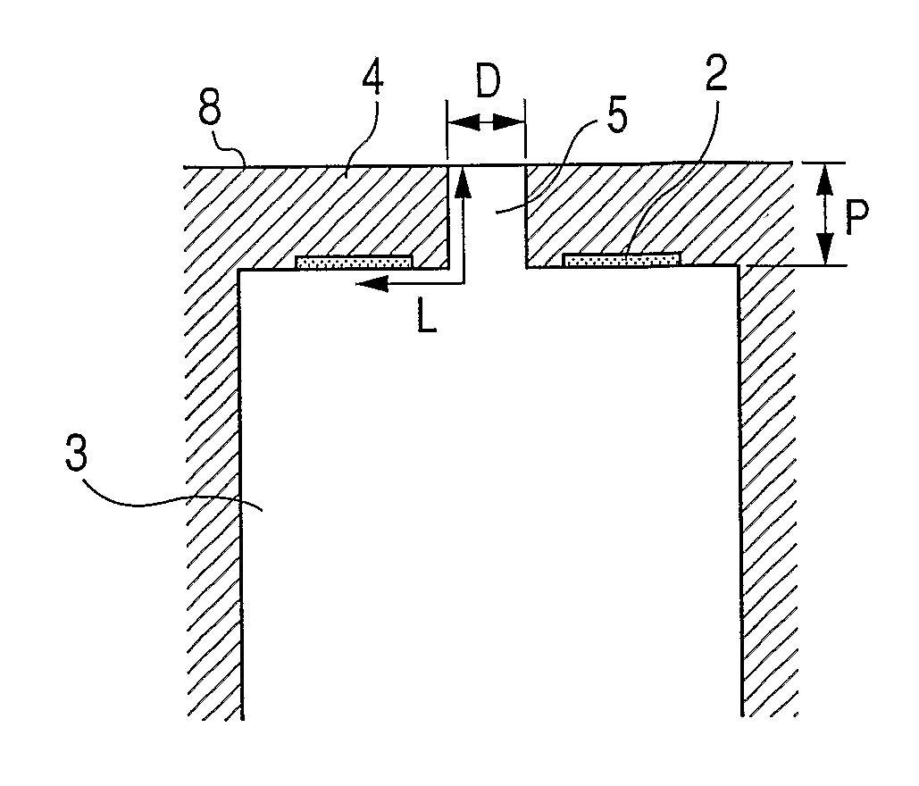
[0024]FIGS. 1 and 2 are views showing the main components of the ink jet recording head of the present embodiment. FIG. 1 is a sectional view of the periphery of a discharge port 5, and FIG. 2 is a top plan view of an orifice plate 4 seen from a liquid discharge surface 8 side. In FIG. 2, a heat generating element 2 and a flow path 3 are disposed at the rear surface of an orifice plate 4, and normally invisible from this direction. However, for ease of description, their positions are depicted through the orifice plate 4. Further, in each drawing, the details such as an electric wiring for driving the heat generating element 2 are not illustrated.

[0025]As apparent from FIGS. 1 and 2, the basic structure of the ink jet recording head of the present embodiment is a so-called backshooter structure providing the heat generating element 2 at the rear surface (surface opposite to liquid discharge surface 8) of the orifice plate 4 having a discharge port 5.

[0026]The heat generating element...

second embodiment

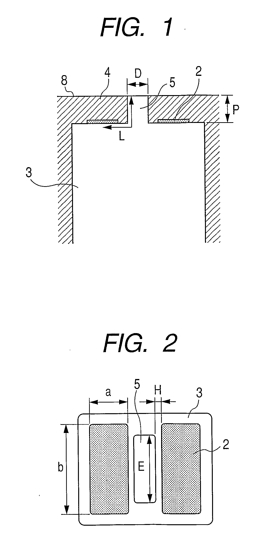
[0060]FIGS. 5 and 6 are views showing main components of an ink jet recording head of the present embodiment. FIG. 5 is a sectional view of the periphery of a discharge port 5, and FIG. 6 is a top plan view of an orifice plate 4 seen from a liquid discharge surface 8 side. In these drawings, the same parts as the first embodiment are provided with the same reference numerals, and the detailed description thereof will be omitted.

[0061]The present embodiment is different in the configuration of a flow path 3 from the first embodiment, and the flow path 3 extends in a direction parallel with the liquid discharge surface 8. Further, the discharge port 5 is circle in the present embodiment.

[0062]As a heat generating element 2, two rectangular elements are provided, and they are disposed at the positions opposite each other by sandwiching the circular discharge port 5. Each heat generating element 2 is disposed such that one of the long sides is opposed to the discharge port 5, and the lo...

third embodiment

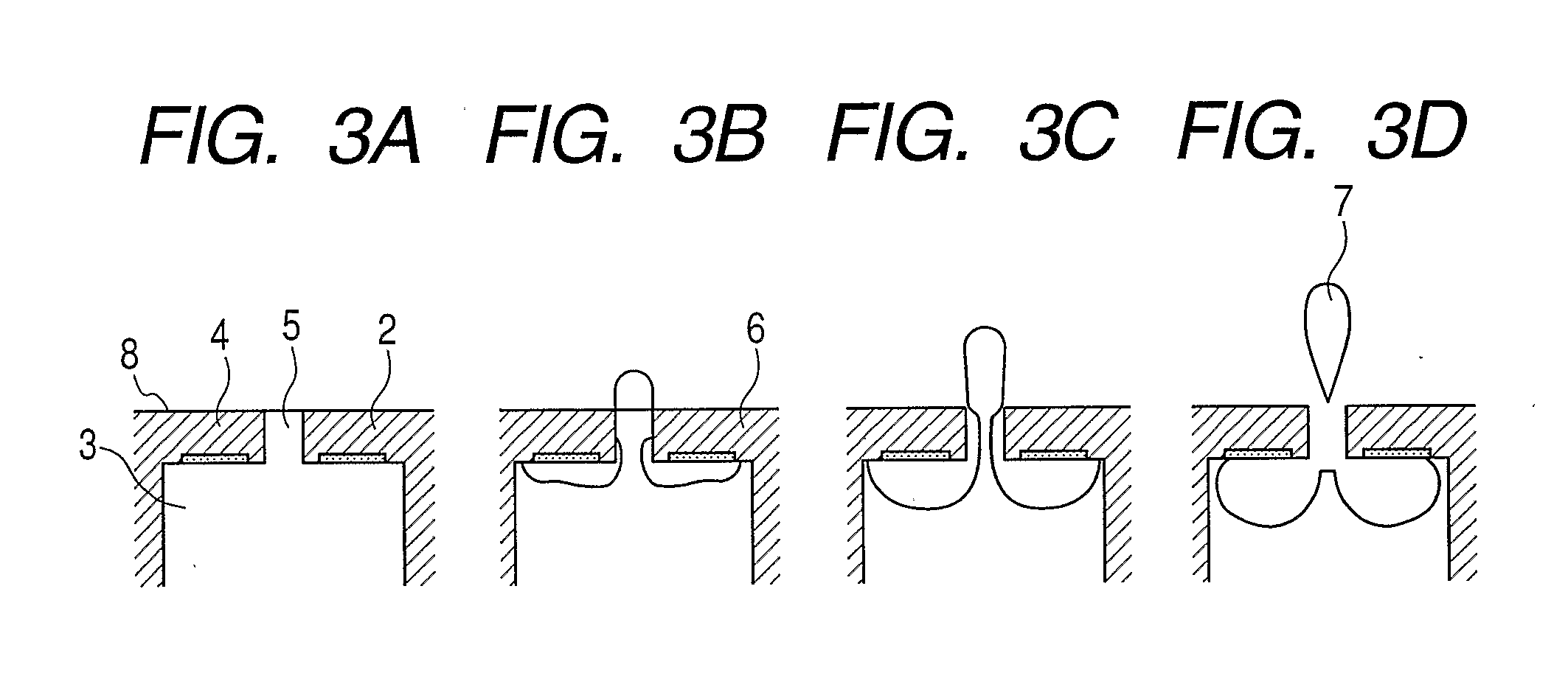
[0071]FIG. 8 is shown a sectional view of main components of an ink jet recording head of the present embodiment. In the drawing, the same parts as the first and second embodiments are provided with the same reference numbers, and the detailed description thereof will be omitted.

[0072]A heat generating element 2 provided at the rear surface of an orifice plate 4 needs not to be disposed in parallel with a liquid discharge surface 8 of the orifice plate 4. In the present invention, a head may be configured to allow the bubble generated from each heat generating element 2 to advance into a discharge port 5 and enable a top end of each bubble to reach up to the liquid discharge surface 8 of the orifice plate 4. The present embodiment is such an example, and the orifice plate 4 includes an inclined surface allowing a distance from the liquid discharge surface 8 to be longer as isolated from the discharge port 5 at the opposite side of the liquid discharge surface 8, and the heat generat...


PUM


Abstract

A liquid discharge method allowing a liquid inside a flow path to be heated by a heat generating element (2), thereby to generate a bubble by using a liquid discharge head including an orifice plate (4) having a discharge port (5), heat generating elements symmetrically disposed on the surface opposite to the liquid discharge surface of the orifice plate with the discharge port as a center, and the flow path communicating with the discharge port, and allowing liquid discharged from the discharge port by a volume change accompanied with a generation of bubble, wherein bubble is allowed to advance into the discharge port, and a top end of bubble is allowed to reach at least up to liquid discharge surface (8) of the orifice plate, and a columnar liquid inside the discharge port sandwiched between bubbles is separated by a contraction force caused by a surface tension toward the center of the discharge port.

Description

TECHNICAL FIELD[0001]The present invention relates to a liquid discharge method and a liquid discharge apparatus which granularly discharge a liquid such as an ink by using heat energy, and in particular, it relates to an ink jet recording method and an ink jet recording head which perform recording by discharged ink droplets.BACKGROUND ART[0002]As an ink jet recording method, there is a known method in which, by giving heat energy to an ink, the ink is induced to cause a change of state followed by the volume change (generation of bubbles), and the ink is discharged by an acting force based on this change of state. The discharged ink is adhered on a recording medium, thereby performing an image formation.[0003]As one of the basic structures of the recording head for performing the ink discharge, there are structures such as disclosed in U.S. Pat. Nos. 5,841,452, 6,499,832, and 7,101,024. This structure, as shown in FIGS. 9A to 9D, is a structure in which the rear surface (the ink f...

Claims


Application Information

Patent Timeline
Patent Type & Authority Applications(United States)
IPC IPC(8): B41J2/14B41J2/05
CPCB41J2/14137B41J2002/1437B41J2002/14169
Inventor INOUE, TAKASHITAMURA, YASUYUKI
Owner CANON KK
Why Eureka
Try Eureka