Display Device Having Touch Sensor and Method of Driving the Same

a display device and touch sensor technology, applied in the field of display devices having touch sensors, can solve the problems of increased manufacturing cost, limited design of display devices, and deterioration of mobility of display devices, so as to reduce noise and sensing time

Active Publication Date: 2012-03-08
LG DISPLAY CO LTD
View PDF12 Cites 206 Cited by
  • Summary
  • Abstract
  • Description
  • Claims
  • Application Information

AI Technical Summary

Benefits of technology

[0012]One object of the present invention is to provide a display device that time divides and alternately drives an in-cell touch sensor and a display area, thereby reducing the occurrence of noise and sensing time, and also a method of driving the same.

Problems solved by technology

However, the touch panel is manufactured separately from the display device, resulting in increased manufacturing cost.
As a result, the mobility of the display device is deteriorated.
Furthermore, the display device is restricted in design.
In the in-cell type touch sensor mounted in a pixel array of the display device, however, it is not possible to drive the display device and the touch sensor at the same time.

Method used


Image

  • Display Device Having Touch Sensor and Method of Driving the Same
  • Display Device Having Touch Sensor and Method of Driving the Same
  • Display Device Having Touch Sensor and Method of Driving the Same

Examples


Embodiment Construction

[0030]Reference will now be made in detail to the specific embodiments of the present invention, examples of which are illustrated in the accompanying drawings. Wherever possible, the same reference numbers will be used throughout the drawings to refer to the same or like parts. Detailed description of known arts is omitted if it is determined that the arts can mislead the present invention.

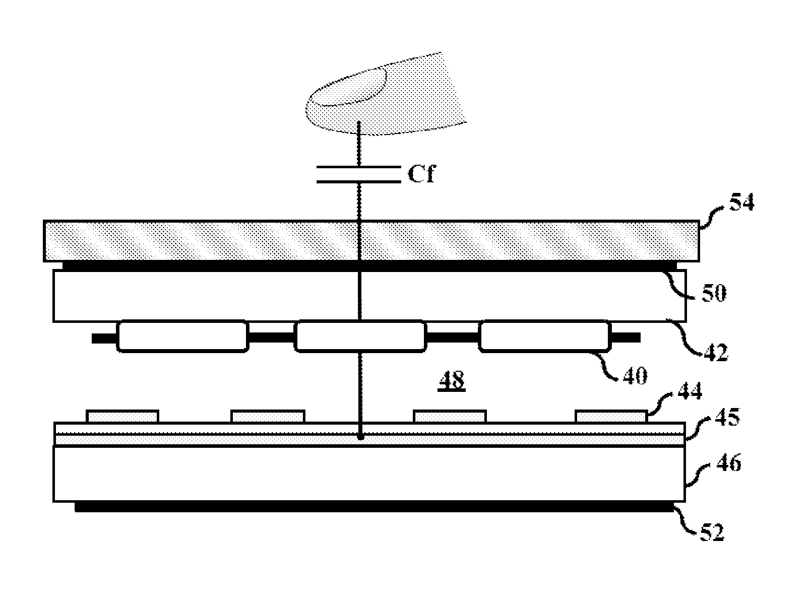
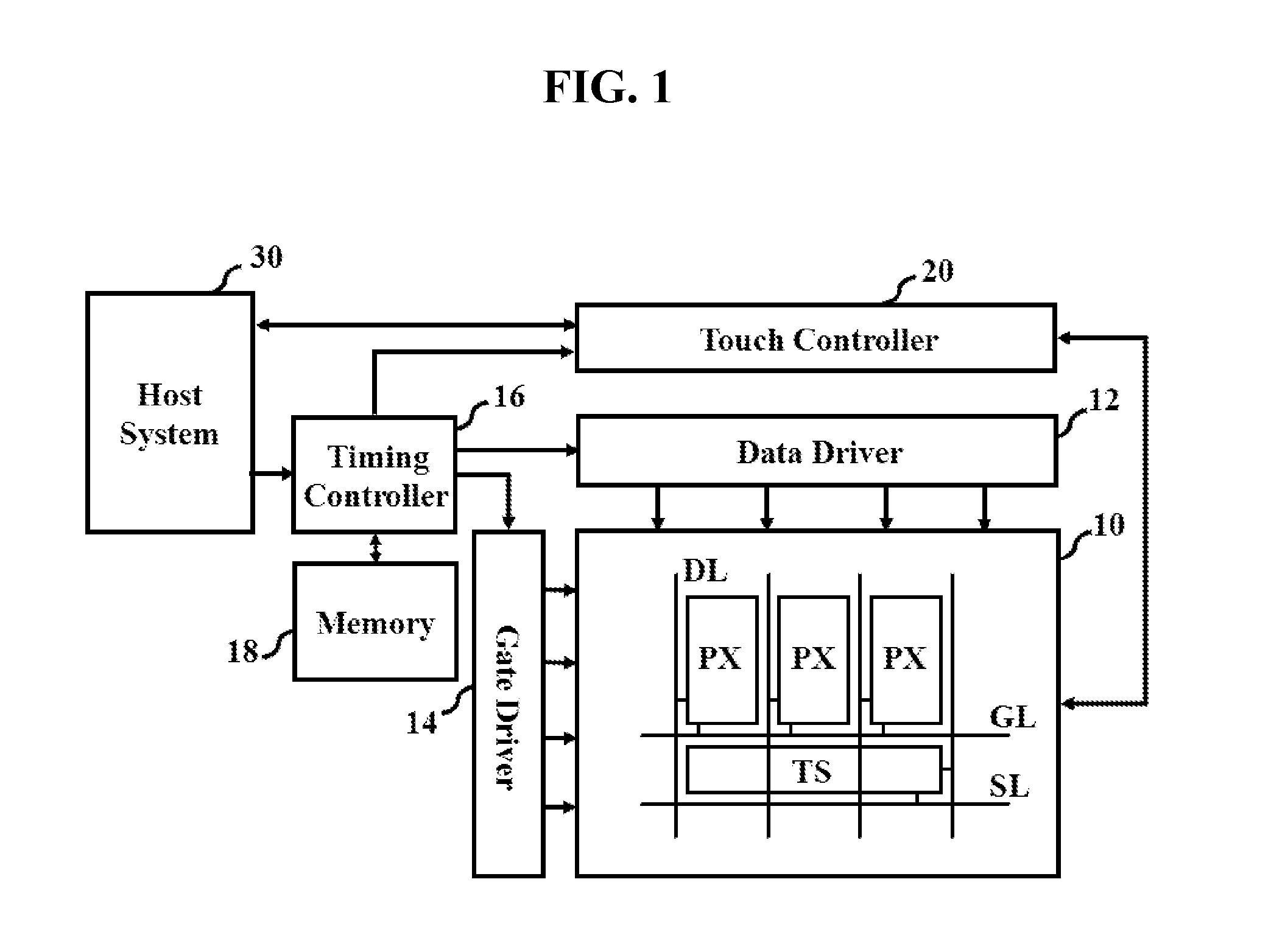
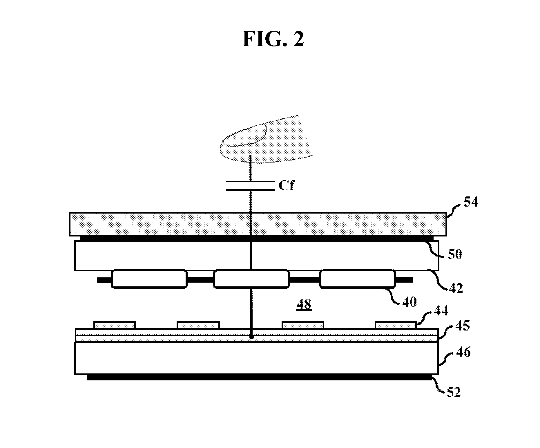
[0031]FIG. 1 is a block diagram schematically showing a drive unit of a display device having touch sensors according to an embodiment of the present invention and FIG. 2 is a sectional view showing the vertical structure of a display panel 10 shown in FIG. 1.

[0032]Referring to FIG. 1, the display device includes a display panel 10 in which touch sensors TS are mounted, a data driver 12 and a gate driver 14 to drive the display panel 10, a timing controller 16 to control a panel drive unit including the data driver 12 and the gate driver 14, and a touch controller 20 to control the touch sensors ...


PUM


Abstract

A display device having touch sensors and a method of driving the same are disclosed. The display device includes a display panel including a pixel array including pixels and a touch sensor array including touch sensors formed in the pixel array, the pixel array being divided into blocks, a gate driver to sequentially drive a plurality of gate lines in the pixel array in a block unit, a data driver to drive a plurality of data lines in the pixel array when the gate lines are driven, a touch controller to sequentially drive the touch sensor arrays in the block unit, and a timing controller to divide one frame into at least one display mode at which the pixel array is driven and at least one touch sensing mode at which the touch sensor array is driven and to control the gate drive, the data driver and the touch controller so that the display mode and the touch sensing mode alternate.

Description

[0001]This application claims the benefit of Korean Patent Application No. 10-2010-0088117, filed on Sep. 8, 2010, which is hereby incorporated by reference in its entirety.BACKGROUND OF THE INVENTION[0002]1. Field of the Invention[0003]The present invention relates to a display device having a touch sensor, and more particularly to a display device that divides a period of time and alternately drives a touch sensor and a display area, thereby reducing the occurrence of noise and sensing time, and a method of driving the same.[0004]2. Discussion of the Related Art[0005]In recent years, a touch sensor (e.g. a touch screen or a touch panel) enabling information to be input by a touch on screens of various kinds of display devices has been widely used as an information input device for computer systems. The touch sensor enables a user to simply touch a screen through a finger or a stylus to move or select information displayed on the screen. Consequently, people of all ages and both se...

Claims


Application Information

Patent Timeline
Patent Type & Authority Applications(United States)
IPC IPC(8): G06F3/041
CPCG06F3/0412G06F3/044G06F3/042G06F3/04184G09G3/20G09G3/36G06F2203/04103G06F3/04166G09G3/3266G09G3/3275G09G3/3677G09G3/3688G09G2310/08
Inventor CHOO, KYO-HYUCKSEO, JUNG-HOONHWANG, SANG-SOOKIM, SUN-YEOP
Owner LG DISPLAY CO LTD
Why Eureka
Try Eureka