Reuse of a physical control channel in a distributed cellular radio communication system

a radio communication system and control channel technology, applied in the field of physical control channels in distributed cellular radio communication systems, can solve the problems of reducing contention in cells, but the cell population is small, and the effect of reducing the number of contentions

Inactive Publication Date: 2000-08-22
TELEFON AB LM ERICSSON (PUBL)
View PDF14 Cites 202 Cited by
  • Summary
  • Abstract
  • Description
  • Claims
  • Application Information

AI Technical Summary

Benefits of technology

Another object is to reduce the occurrences of contention in a cell.
The generated logical control channels are mapped, according to a predetermined map, onto the physical downlink control channel of the respective radio unit and are transmitted from the radio units to the mobile stations. It follows that different radio units can transmit different information on the physical downlink control channel, which may therefore be reused in the cell. A maximum of one connection per radio unit may be established, which increases the capacity with respect to the number of connections established per time unit.
An advantage of the present invention is that more connections may be established per time unit in a distributed cell, which leads to an increased capacity in a distributed cellular radio communication system.
Another advantage arises when the physical control channel is reused in the uplink direction, which reduces the number of contention occurrences.

Problems solved by technology

The cells are, however, very small, and cover, for example, one floor of a building.
However, only one mobile station within a cell can request access at any given time, and only one mobile station can establish a new connection at a given time.
Another problem is how the occurrence of contention in a cell can be reduced.
More specifically, the problems are solved in that each radio unit in the distributed cellular radio communication system receives signals on physical uplink channels.

Method used


Image

  • Reuse of a physical control channel in a distributed cellular radio communication system
  • Reuse of a physical control channel in a distributed cellular radio communication system
  • Reuse of a physical control channel in a distributed cellular radio communication system

Examples


Embodiment Construction

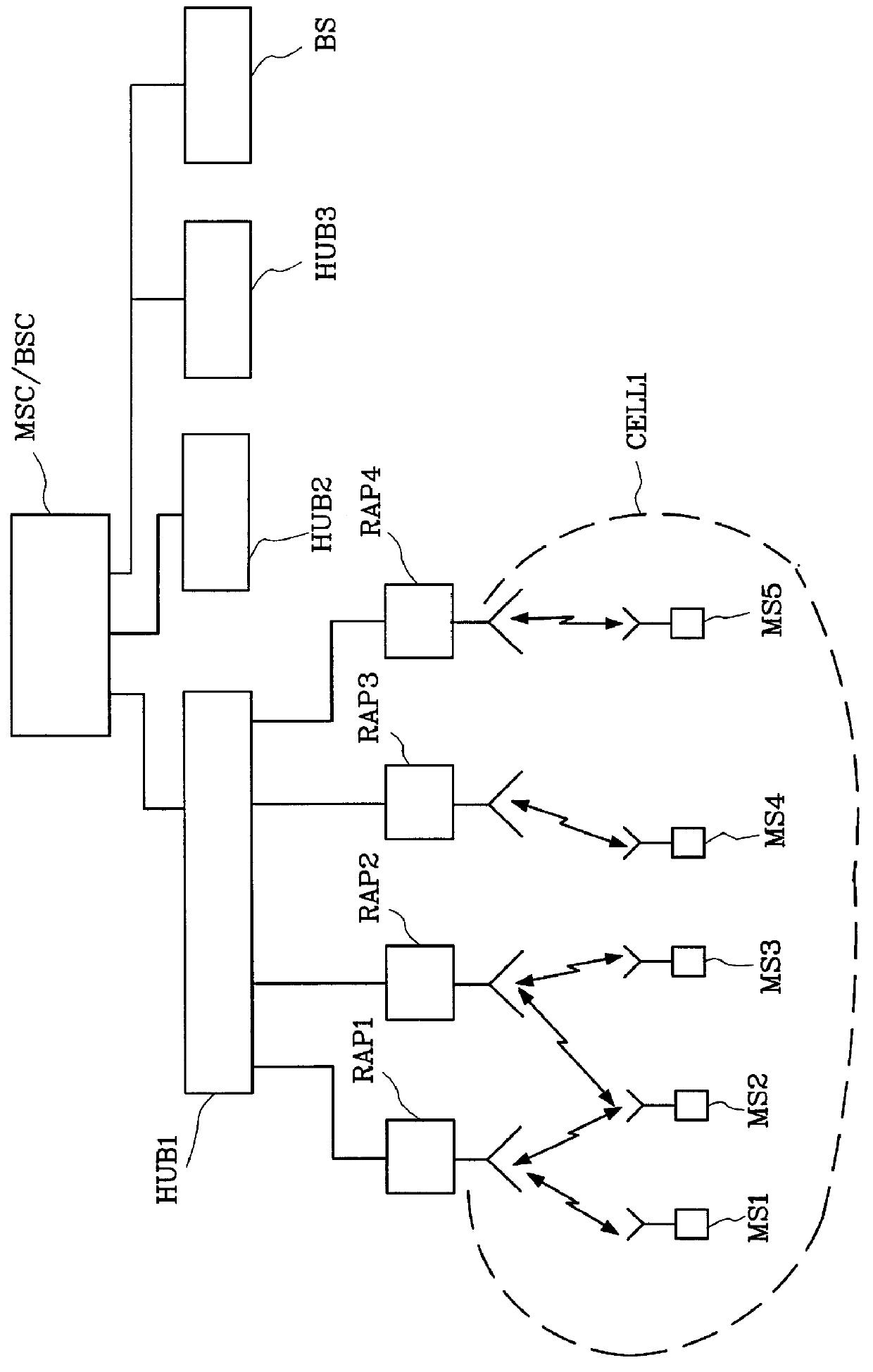
FIG. 1 shows schematically a cellular radio communication system comprising distributed radio units according to prior art. The system comprises a mobile switching centre MSC, alternatively a base station switching centre BSC, controlling a number of central units HUB1-HUB3, and in the present case also a conventional base station BS. Each central unit HUB1-HUB3 in turn controls a number of distributed radio units RAP1-RAP3. It is also possible for a distributed cell to comprise more than one central unit. In the present system there are both cells comprising distributed radio units and cells comprising conventional base stations. The system illustrated in FIG. 1 thus comprises three distributed cells, only one CELL1 of which is shown in detail.

In a cell CELL1 a number of radio units RAP1-RAP4 are placed. Each radio unit comprises transmitter and receiver devices. The radio units RAP1-RAP4 in a cell are controlled by the central unit HUB1 in this cell. The radio units communicate wi...


PUM


Abstract

The present invention relates to the reuse of a control channel in a distributed cellular radio communication system. At least one physical channel, the so called physical control channel, in the radio communication system is used for transferring logical control channels. According to the present invention the physical uplink control channel can be reused with respect to logical control channels comprising an access request. The physical downlink control channel can be reused with respect to logical control channels comprising a message that access is granted to a mobile station or a message that someone requests contact with a mobile station. According to the invention the physical uplink control channel and / or the physical downlink control channel is reused. This means that more connections per time unit may be established in the radio communication system.

Description

The present invention relates to a method for the reuse of a physical control channel in a cell in a cellular distributed radio communication system. The invention also relates to a distributed cellular radio communication system in which the method is utilized. More specifically, the invention relates to the reuse of a physical control channel in a cell when the information being transmitted on the physical control channel does not need to have coverage in the whole cell.DESCRIPTION OF RELATED ARTCellular mobile radio communication systems normally comprise a number of mobile stations communicating with base stations through radio channels. A number of base stations are in turn controlled by a base station switching centre. Distributed cellular radio communication systems are systems comprising antennas or radio units distributed within a cell. The distributed antennas or radio units in a cell are controlled by at least one central unit which may in turn be controlled by a base sta...

Claims


Application Information

Patent Timeline
Patent Type & Authority Patents(United States)
IPC IPC(8): H04Q7/38H04W72/04H04W74/08
CPCH04W74/002
Inventor WIOREK, JONASFRODIGH, MAGNUSBEMING, PERWALLSTEDT, KENNETH
Owner TELEFON AB LM ERICSSON (PUBL)
Why Eureka
Try Eureka