Method and apparatus for treating heart failure

a heart failure and heart failure technology, applied in the field of heart failure prevention or remediation, can solve the problems of loss of pump function, cardiac dilation, and overflow of blood volume, and achieve the effects of reducing stroke occurrence, preventing cryptogenic stroke, and reducing left atrial pressur

Inactive Publication Date: 2005-07-28
BUILDING ADDRESS
View PDF6 Cites 210 Cited by
  • Summary
  • Abstract
  • Description
  • Claims
  • Application Information

AI Technical Summary

Benefits of technology

[0022] The invention is a left atrial pressure relief system for reducing left atrial pressures and left ventricular end diastolic pressures (LVEDP). The system consists of an interatrial septal conduit with an emboli barrier or trap mechanism to prevent cryptogenic stroke due to thrombi or emboli crossing the conduit into the left sided circulation. A wire mesh may serve as one emboli barrier design. Alternatively, a one-way valve with an opening pressure of at least 1 mm Hg may be used to reduce s...

Problems solved by technology

Loss of pump function leads to cardiac dilation, blood volume overload, pulmonary congestion, and ultimately organ failure.
Systolic failure is primarily loss of left ventricular contractility leading to reduced delivery of blood to the body.
Diastolic failure is due to a loss of compliance of the left ventricle, which limits blood filling during diastole.
This leads to mechanical changes in the heart such as reduced compliance, reduced contractility, or both.
Increases in LVEDP ultimately cause increases in left ventricular wall stress.
However, even after the adaptive response, the diseased heart is typically subjected to repeated episodes of increased LVEDP and wall stress.
The left atrium can undergo similar hypertrophy and dilation that ultimately lea...

Method used


Image

  • Method and apparatus for treating heart failure
  • Method and apparatus for treating heart failure
  • Method and apparatus for treating heart failure

Examples


embodiment 200

[0046] Preferably, a self-expandable embodiment 200 would be used, which would expand due to the presence of a filter 204 on the end of the tube 202, as shown in FIG. 4. A polyester, Goretex™, or Dacron™ graft / sheath 210 could be placed around and sewn onto the tubular structure, such as an expandable wire frame 212, or within the tubular structure 212, to prevent blood leakage and promote endothelialization.

[0047] To prevent cryptogenic stroke, filters or traps or wire mesh structures 204 can be placed on both ends or on one end of the tubular structure 212. The wire filter / mesh or emboli barriers would prevent large emboli from crossing the septum and entering the left sided circulation. The barriers 204 could be integral to the tubular structure and could serve to anchor the tube 202 across the septum. If a barrier 204 were used on only one end, such as the right end, a strut 214 for anchoring the conduit 202 to the atria on the left end would be used. This strut 214 could be des...

embodiment 300

[0048] As in the embodiment 300 shown in FIGS. 5a and 5b, the filter 304 can be a mesh-like design that would collapse into a transseptal delivery catheter 316 and would deploy by expanding larger than the tube conduit 302. The embolic barrier would have a pore size of 0.1 to 2.0 mm or greater. A wire mesh design could flatten out against the septum or remain globular on each end. Alternatively, a porous polymer supported on expandable struts could also serve as a barrier. Alternatively, a flat spiral design could be deployed that would also anchor the conduit to the septum. The spiral would have 0.1 to 2.0 mm spacing between successive turns. Other mechanisms to filter or prevent thrombi from crossing the conduit from the right to the left could be employed.

[0049] A mechanism for attaching the device 300 to a stylet 318, that would be used to push and pull the device 300 during deployment, would be connected to the right or left atrial filter / mesh structure 304 or both. One embodim...

embodiment 400

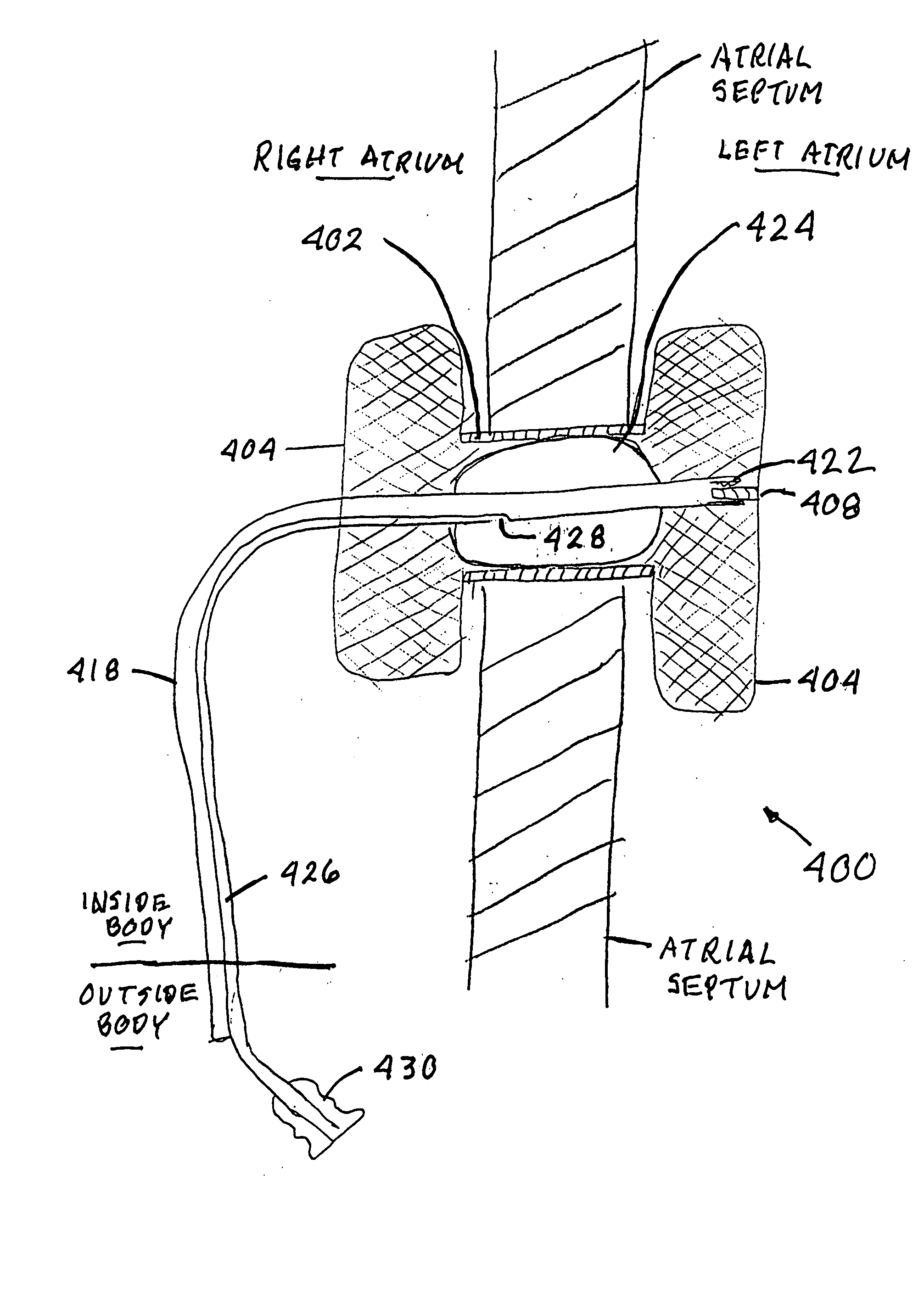
[0051] As seen in the embodiment 400 of FIG. 6, to control the opening of the conduit 402 after placement of the device 400, the stylet 418 in some embodiments may have an expandable and collapsible balloon 424 on the section of the stylet 418 that resides substantially within the conduit 402 and between the filters 404. As before, the connector 422 on the distal end of the stylet 418 would be threaded onto the threaded extension 408 on the left end filter 404. The interior of the balloon 424 would be in fluid communication with a balloon inflation channel 426 within the stylet 418. This channel 426 would be in fluid communication with a balloon inflation port 428 that would allow saline to be delivered to or withdrawn from the balloon 424, using a syringe 430 or some other fluid injection and withdrawal device. This would allow the balloon 424 to be inflated and deflated as necessary. This balloon 424 may also be used to expand the conduit 402 in the balloon expandable designs. Pre...


PUM


Abstract

An apparatus for treating heart failure, including a conduit positioned in a hole in the atrial septum of the heart, to allow flow from the left atrium into the right atrium. The conduit is fitted with one or more emboli barriers or one-way valve members, to prevent thrombi or emboli from crossing into the left side circulation.

Description

CROSS REFERENCE TO RELATED APPLICATIONS [0001] This application relies upon U.S. Provisional Patent Application No. 60 / 525,567, filed on Nov. 26, 2003, and entitled “Left Atrial Pressure Relief System for CHF”; U.S. Provisional Patent Application No. 60 / 532,983, filed on Dec. 29, 2003, and entitled “Method for Treating Heart Failure”; U.S. Provisional Patent Application No. 60 / 539,673, filed on Jan. 27, 2004, and entitled “Method for Treating Heart Failure”; and U.S. Provisional Patent Application No. 60 / 615,880, filed on Oct. 5, 2004, and entitled “Method for Treating Heart Failure”.STATEMENT REGARDING FEDERALLY SPONSORED RESEARCH OR DEVELOPMENT [0002] Not Applicable BACKGROUND OF THE INVENTION [0003] 1. Field of the Invention [0004] This invention is in the field of prevention or remediation of heart disease. [0005] 2. Background Art [0006] The human heart delivers oxygenated blood to the organs of the body to sustain metabolism. The human heart has four chambers, two atria and tw...

Claims


Application Information

Patent Timeline
IPC IPC(8): A61F2/01A61F2/02A61F2/06A61F2/24A61M5/00A61M39/24
CPCA61F2/01A61F2/064A61F2/24A61F2230/0006A61M39/24A61F2230/0078A61F2002/018A61F2/2493A61M27/002A61F2/012A61F2/2476
Inventor DOBAK, JOHN D. III
Owner BUILDING ADDRESS
Why Eureka
Try Eureka