Image forming apparatus

a technology of forming apparatus and forming chamber, which is applied in the direction of electrographic process apparatus, instruments, optics, etc., can solve the problems of increasing reducing the service life requiring a certain length of time to raise the temperature of the heating member, so as to reduce the waiting time and ensure the fixation effect of the imag

a technology of forming apparatus and forming chamber, which is applied in the direction of electrographic process apparatus, instruments, optics, etc., can solve the problems of increasing reducing the service life requiring a certain length of time to raise the temperature of the heating member, so as to reduce the waiting time and ensure the fixation effect of the imag

US20060088330A1Inactive Publication Date: 2006-04-27KONICA MINOLTA BUSINESS TECH INC

Image

  • Image forming apparatus
  • Image forming apparatus
  • Image forming apparatus

Examples


Embodiment Construction

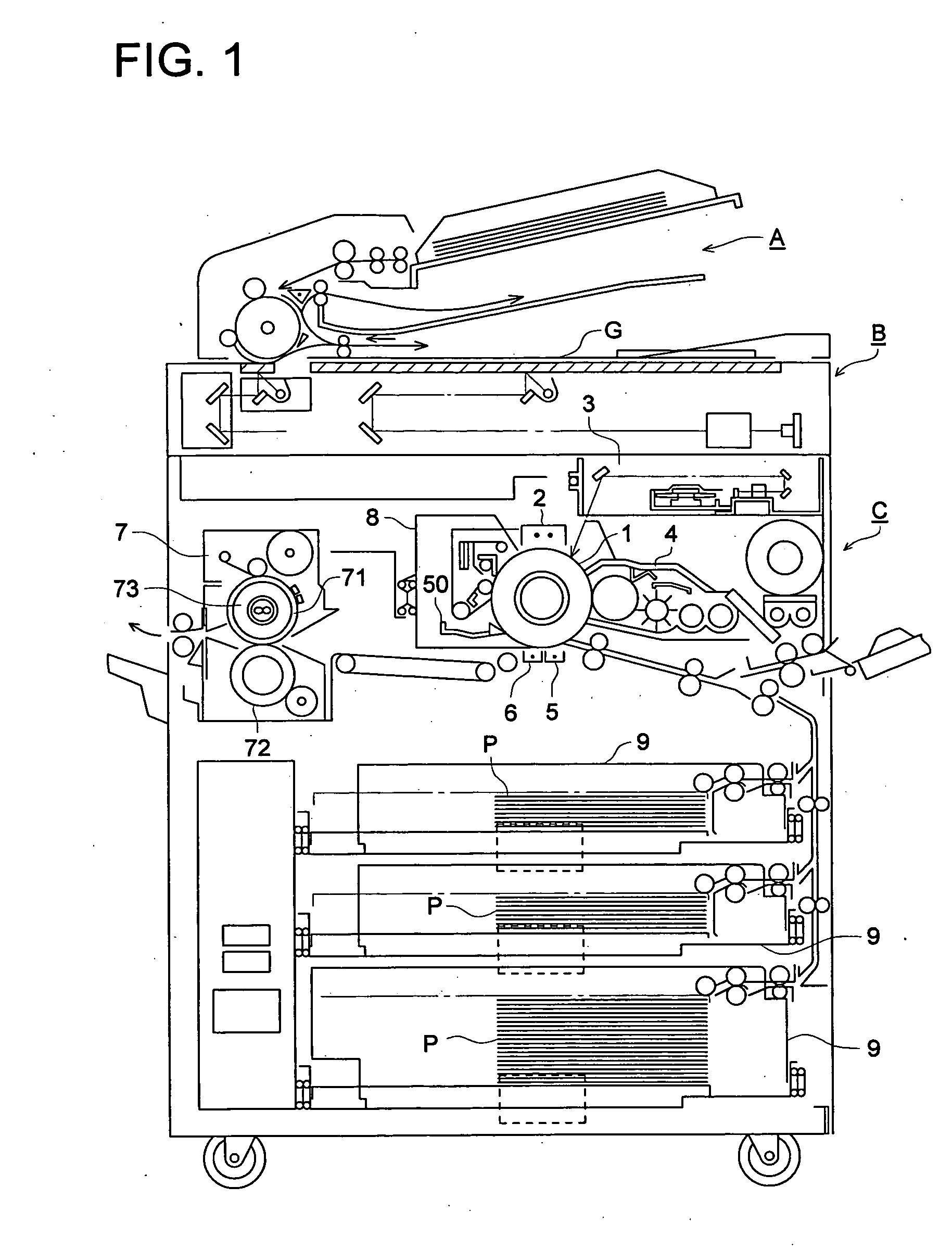
[0026]FIG. 1 shows the mechanical configuration of the image forming apparatus according to a preferred embodiment of the present invention.

[0027] The image forming apparatus includes an automatic document transportation apparatus A, an image reading section B, and an image forming section C. In the image forming section C, the numeral 1 indicates the photosensitive body, and, from the point of view of environment friendliness and cost, although it is preferable to use an organic photosensitive body having a photosensitive layer made of an organic photoconductive material dispersed in resin, it is not necessary to restrict to this but it is possible to use any widely known photosensitive body.

[0028] In addition, it is not necessary to restrict the photosensitive body 1 to be a drum shaped photosensitive body as is shown in the figure, but it can also be of the belt shape. The numeral 2 in the figure indicates the charging means that form a uniform electric potential on the surface...


PUM


Abstract

An image forming apparatus, provided with a fixing device that transports the recording material while gripping it using a heating member and a pressing member and that carries out fixing by heating from the heating member, has a driving device for rotating the heating member and the pressing member and a controller that controls the driving device in an idling state so that the heating member and the pressing member turn into a printing standby state during which the heating member and the pressing member carry out an idling rotation when a specific external operation is made.

Description

[0001] This application claims priority from Japanese Patent Application No. 2004-312089 filed on Oct. 27, 2004, which is incorporated hereinto by reference. BACKGROUND OF THE INVENTION [0002] The present invention relates to an image forming apparatus in use of an electro-photographic method. [0003] In an image forming apparatus of the electro-photographic method, a thermal fixing means that carry out thermal fixing are used very widely as the fixing means that fixes an unfixed toner image on a recording medium. It is very common that the thermal fixing means requires time after supplying the power to it until it reaches a specific fixing temperature. In other words, in a regular image forming apparatus, after the main power switch has been switched ON, the image forming apparatus cannot go into the state in which image forming is possible unless a certain has elapsed. [0004] On the other hand, from the point of view of suppressing the power consumption or of preventing the effect ...

Claims


Application Information

Patent Timeline
27 Apr 2006
Publication
US20060088330A1
IPC
G03G15/20
CPC
G03G15/205
Inventors
FUJITA, SHINSUKE