
Head unit, droplet discharging apparatus, droplet discharging system, information processing apparatus, information processing method, status information notifying method, status information updating method, faulty position detecting method, and programs

a technology for dropping devices and droplets, applied in the field of droplet discharging devices, can solve problems such as clogging of discharge ports, faulty discharges, and degradation of performance of printing machines

Inactive Publication Date: 2005-07-07
SONY CORP
View PDF1 Cites 3 Cited by
  • Summary
  • Abstract
  • Description
  • Claims
  • Application Information

AI Technical Summary

Benefits of technology

[0013] The present invention has been made in view of the above circumstances and has as its principal object the provision of techniques for allowing those engaged in repair work to easily isolate the probable cause of a faulty discharge head.
[0014] Another object of the invention is to provide techniques for allowing service personnel easily to change status information about the discharge head.
[0015] A further object of the invention is to provide arrangements for allowing the end user to verify the probable cause of a defective function with a high degree of confidence without resorting to specialized analytic tools.
[0030] The inventive arrangements outlined above allow service personnel to verify status information about a stand-alone head unit or a head unit incorporated in a droplet discharging apparatus. The service personnel are thus able to grasp the current status of the discharge head and change its status information with little difficulty. This makes it possible to recover easily from a failed function of the discharge head.
[0040] If any defect is detected, the inventive arrangements outlined above enable the information processing apparatus to gain direct access to status information about the connected droplet discharging apparatus for analysis and thereby to present the end user with the probable cause of the defect with a high degree of confidence. This makes it possible for the end user to determine early on whether the trouble can be dealt with on the user's side or needs to be taken care of by service personnel.
[0043] The inventive arrangements allow the end user adequately to fix simple troubles on the spot. The practice saves time and money that would otherwise be needed for the repair by experts. Needless to say, the end user is suitably guided to address the defect with no need to rely on subjective assessments.

Problems solved by technology

Depending on their use status, these printers can sometimes experience cases of degradation in performance.
Notable cases of such degradation include faulty discharges due to clogged discharge ports (i.e., nozzles) or nozzles that have become defective.
The hypothetical dispatch of a printer designer to the locale of the printer in question, however, is obviously unrealistic from a cost effectiveness point of view.
Repairs of some defects are difficult to accomplish except by those well-versed in the printer design.
Manufacturers and venders have been slow to implement arrangements affording service personnel in the field sufficient means and expertise to isolate and deal with problems in diverse degrees of severity with ease, including the difficult cases.
However, the information provided within the framework of conventional technical assistance is mostly limited to basic settings (e.g., version information about a driver) of the printer, indications for urging the user to clean the printer head, and some supplementary knowledge about the printer innards that cannot be appraised from the outside.
In the meantime, the number of the above-mentioned analytic tools deployed in the field is generally small.
Given their limited resources, service personnel are often forced to roughly isolate what appears to be the trouble with the printer, before replacing an entire unit containing the apparently isolated fault.
As a result, the repair tends to cost more and take longer than is acceptable to many end users.

Method used


Image

  • Head unit, droplet discharging apparatus, droplet discharging system, information processing apparatus, information processing method, status information notifying method, status information updating method, faulty position detecting method, and programs
  • Head unit, droplet discharging apparatus, droplet discharging system, information processing apparatus, information processing method, status information notifying method, status information updating method, faulty position detecting method, and programs
  • Head unit, droplet discharging apparatus, droplet discharging system, information processing apparatus, information processing method, status information notifying method, status information updating method, faulty position detecting method, and programs

Examples


first embodiment

[0086] this invention will now be described.

(1) Head Unit

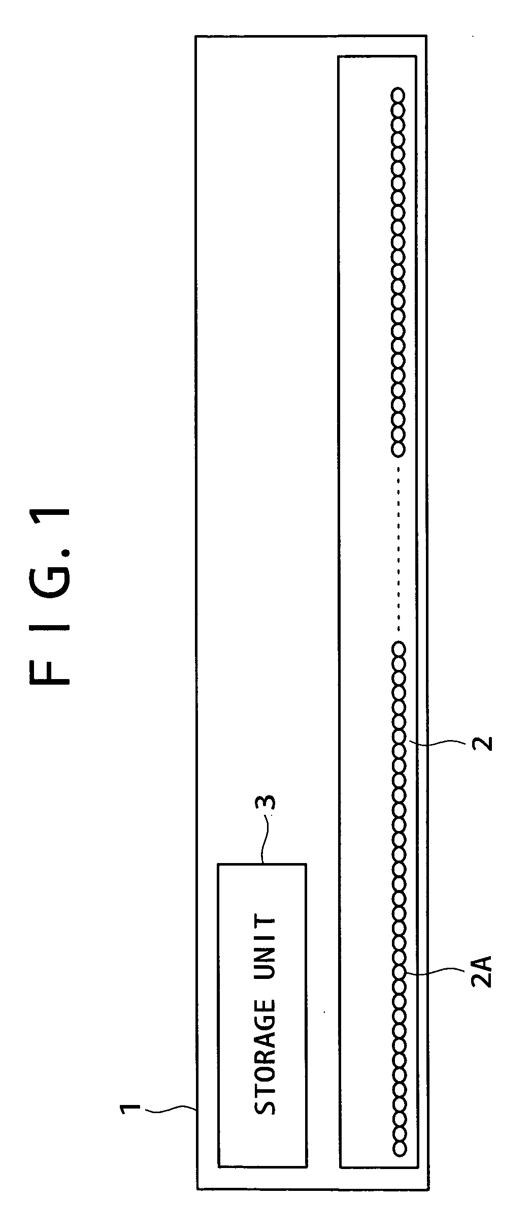
[0087] In order to achieve the foregoing and other objects of this invention, the invention proposes a head unit including the components to be described below. FIG. 1 shows a typical structure of a head unit 1 according to the invention. The head unit 1 includes a discharge head 2 and a storage unit 3. The discharge head 2 has each of its discharge ports 2A discharging droplets at a plurality of pixel areas. The storage unit 3 rewritably retains status information about the discharge head 2.

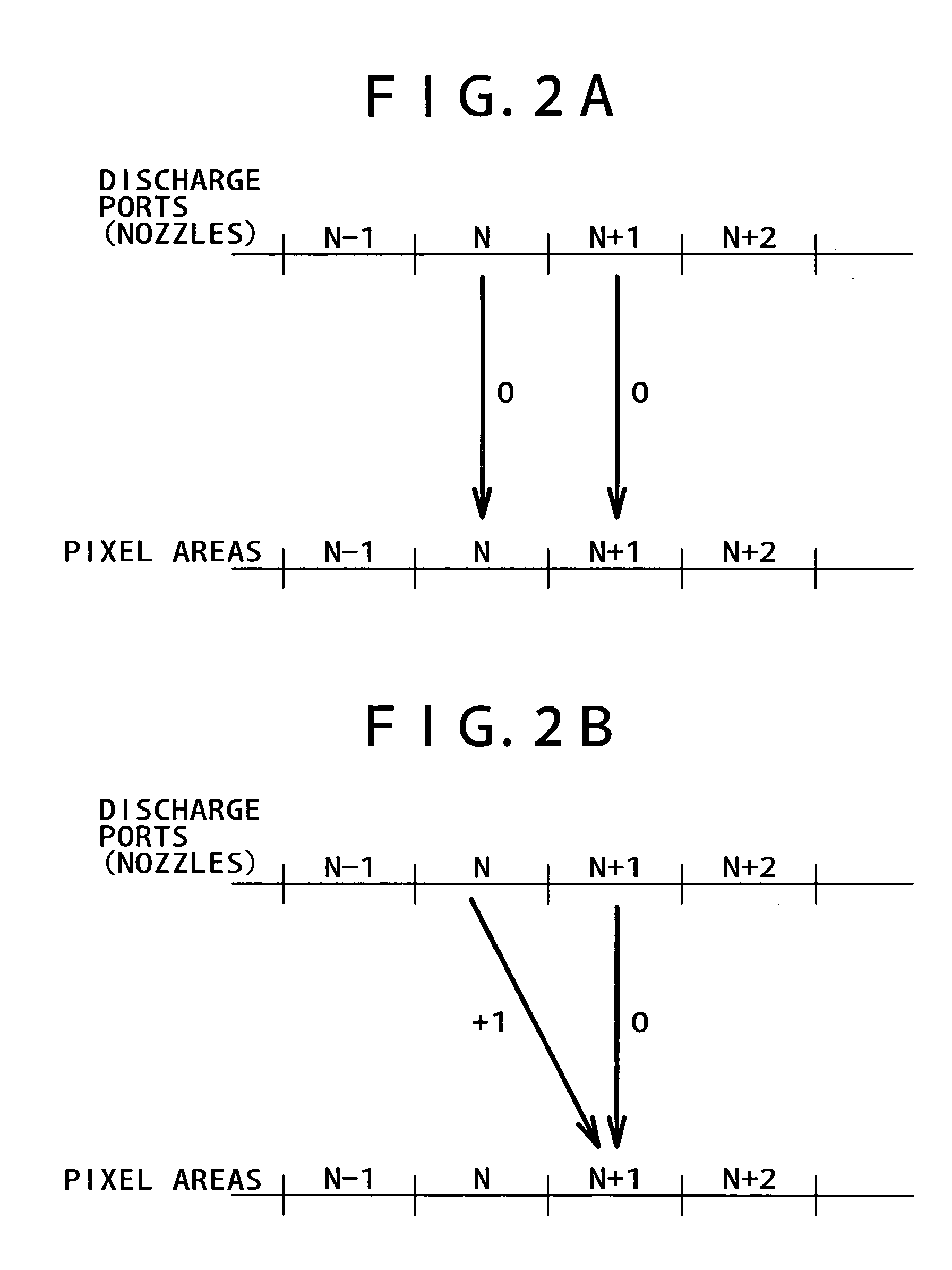
[0088] The head unit 1 uses the discharge ports 2A each capable of discharging droplets not only at a single pixel area but also at a plurality of pixel areas. Illustratively, as shown in FIGS. 2A and 2B, each discharge port may discharge droplets deflectively at two pixel areas. FIG. 2A indicates an example in which deflective discharge is not carried out, while FIG. 2B shows an example in which droplets are discharged deflectively. Th...

second embodiment

[0229] The above and other objectives are brought about by the invention proposed as a droplet discharging apparatus with its major elements described below. FIG. 27 outlines the key components of a droplet discharging apparatus 51 embodying the invention. The droplet discharging apparatus 51 has a detection unit 51A, a storage unit 51B, and a communication unit 51C.

[0230] The detection unit 51A is constituted by hardware or software for detecting changes in status of a monitored object. The hardware may include sensors, switches and / or counters. The software may be composed of programs for determining whether a predetermined threshold value is exceeded by value information collected from the monitored positions. In operation, it is possible for the hardware to detect primary events and then for the software to make secondary decisions on the detected events.

[0231] The detection unit 51A directly collects information about operation status in the object being monitored as well as i...


PUM


Abstract

The present invention provides a droplet discharging apparatus including a discharge head for deflectively discharging droplets through one discharge port at a plurality of pixel areas in adaptive fashion. The discharge head is controlled to discharge droplets at an object. A storage unit stores status information about the discharge head. A communication unit communicates with an information processing apparatus located outside so as to transmit the status information to the information processing apparatus.

Description

BACKGROUND OF THE INVENTION [0001] The present invention relates to a droplet discharging apparatus for discharging droplets at an object. More particularly, the invention relates to: a head unit having a discharge head capable of discharging droplets through a single discharge port at a plurality of pixel areas in deflected fashion; a droplet discharging apparatus equipped with that discharge head; an information processing apparatus capable of communicating adaptively with that droplet discharging apparatus; methods and programs for providing notification and updating status information and for being executed by that droplet discharging apparatus; an information processing apparatus for verifying and updating status information about that droplet discharging apparatus; methods and programs for processing information, detecting faulty positions, and updating status information and for being executed by that information processing apparatus; and a droplet discharging system made up ...

Claims


Application Information

Patent Timeline
Patent Type & Authority Applications(United States)
IPC IPC(8): B41J29/393
CPCB41J29/393
Inventor KOYAMA, MASAYOSHINAKAMURA, MASATONAMEKAWA, TAKUMINISHI, SHOTAHORII, SHINICHI
Owner SONY CORP
Learn More