Folding pinnacle bending device

a technology of folding pinnacles and bending devices, which is applied in the direction of cranes, etc., can solve the problems of high manufacturing costs, inability to replace the hydraulic cylinder version, and inability to meet the requirements of use, and achieve the effect of cost-effectiveness and cost-effectiveness

Active Publication Date: 2006-11-07
MANITOWOC CRANE GROUP FRANCE
View PDF22 Cites 3 Cited by
  • Summary
  • Abstract
  • Description
  • Claims
  • Application Information

AI Technical Summary

Benefits of technology

[0008]One aspect of the present invention is to provide folding pinnacle bending device for a mobile crane, comprising a joint area which is bent in order to adjust the angle of the folding pinnacle and which comprises a joint in its upper or tensile load area, the advantages in accordance with the invention are based on the fact that the joint area comprises a mechanically fixable telescoping means in its lower or pressure load area. In other words, as opposed to the hydraulic cylinder, a non-hydraulic telescoping means is provided in this case, which includes only means which are suitable for mechanically adjusting and fixing it to desired lengths. On the one hand, such a solution offers a relatively cost-effective alternative, since the costs for expensive hydraulic cylinders, for the hydraulic supply and the control and monitoring devices can be spared. On the other hand, such an expensive hydraulic cylinder can easily be replaced by a mechanically fixable telescoping means installed in the lower or pressure load area of the joint area, such that all the steel components of the hydraulically bendable pinnacle can be used and a cost-effective, purely mechanically adjustable folding pinnacle can be provided without too great an outlay, by using a lot of identical parts.
[0010]In one embodiment variant, the telescoping means or telescopic pipe comprises a holding element and an extending element. The holding element is fastened by a joint to the side of the joint area facing the base of the folding pinnacle, and the extending element is fastened by a joint to the side of the joint area facing the tip of the folding pinnacle. Thus, the same fastenings are used in the lower or pressure load area as with hydraulic cylinders, which makes replacing the hydraulic cylinder—as already mentioned above—easily possible. The support elements for the extending element can be arranged on the holding element.
[0011]In the lower or pressure load area, the telescoping means merely has to be configured such that it supports the upper portion, bent against the base of the folding pinnacle. It is sufficient to support the upper portion, it need not necessarily be fixed in both directions, i.e., the upper portion of the folding pinnacle is sufficiently fixed if a support against a further reduction in the angle of the folding pinnacle is provided on one side. This then results in the advantage that the final angle of the folding pinnacle can be set while it is still on the ground, if the jib as a whole—including the folding pinnacle—is placed very near above the ground. In this state, the selected support element is installed, the joint area being low above the ground, to avoid the danger of accidents. Only when the jib is raised is the telescoping means shifted, until the support element blocks and sets a particular angle. It is thus possible to simply and safely set the angle of the folding pinnacle in advance, on the ground.

Problems solved by technology

Disadvantageously, however, high manufacturing costs are incurred, which are not always acceptable.
The disadvantage of such a construction is that it cannot replace the hydraulic cylinder version (FIG. 2) without major alterations.

Method used


Image

  • Folding pinnacle bending device
  • Folding pinnacle bending device
  • Folding pinnacle bending device

Examples


Embodiment Construction

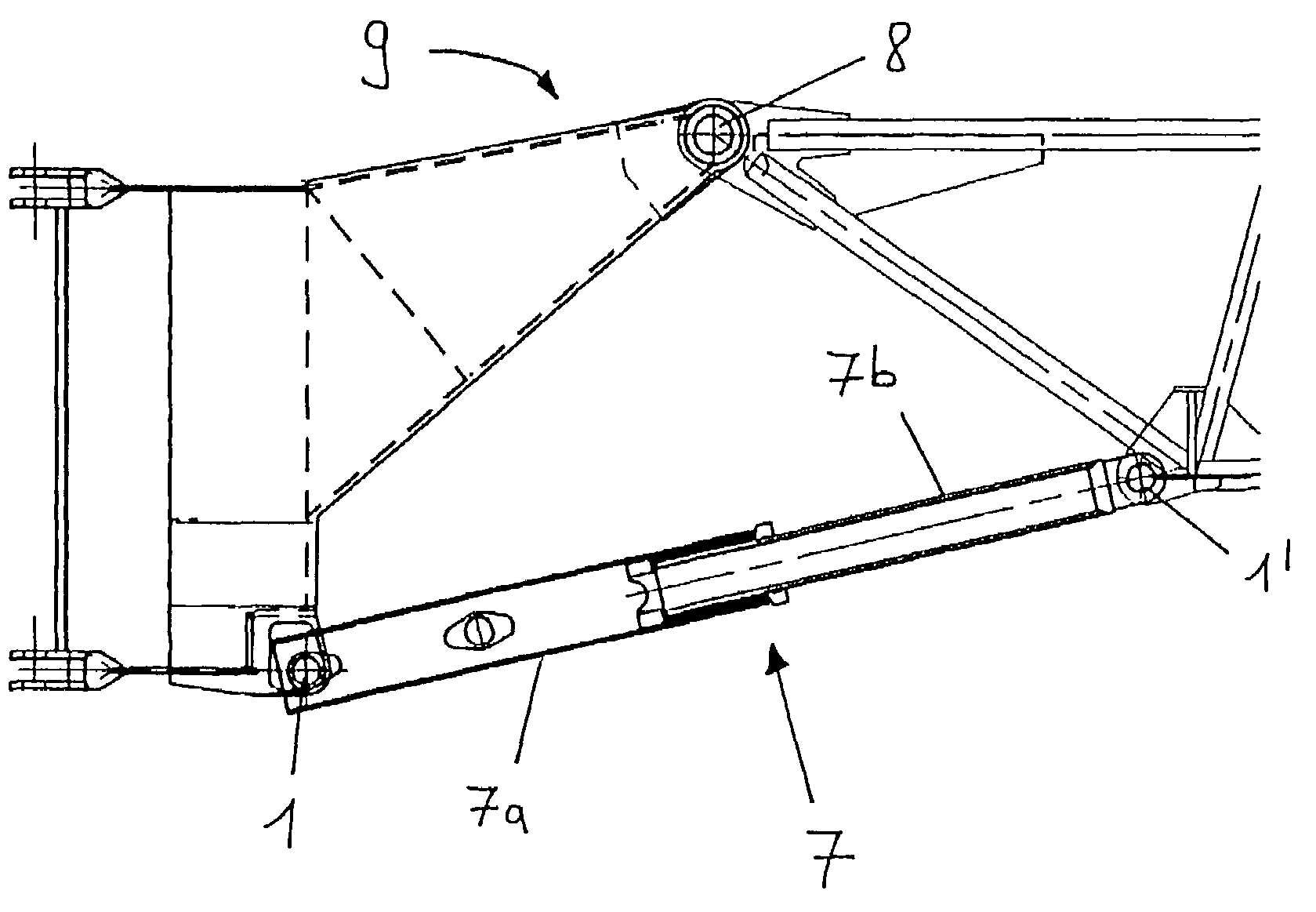
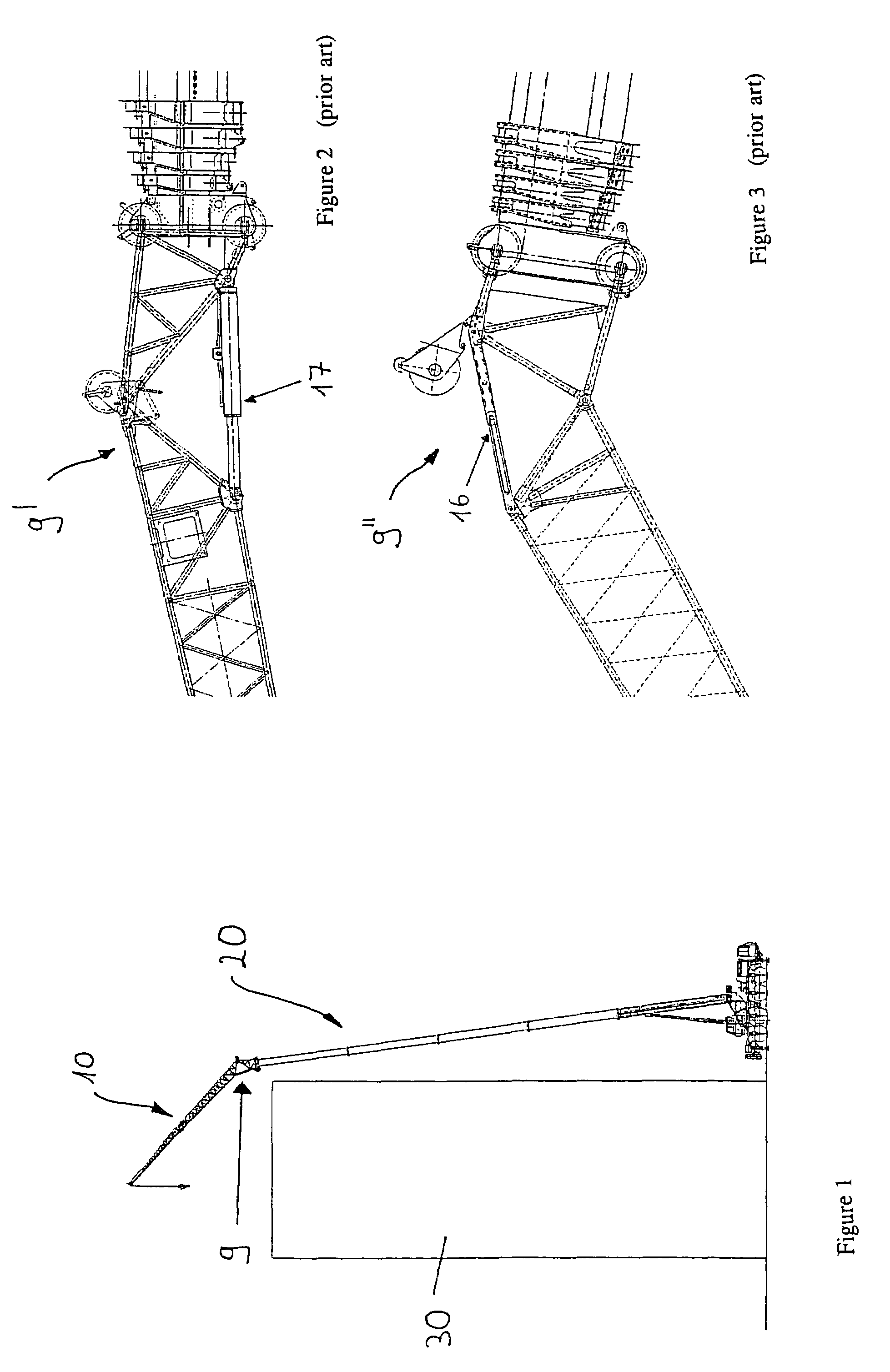
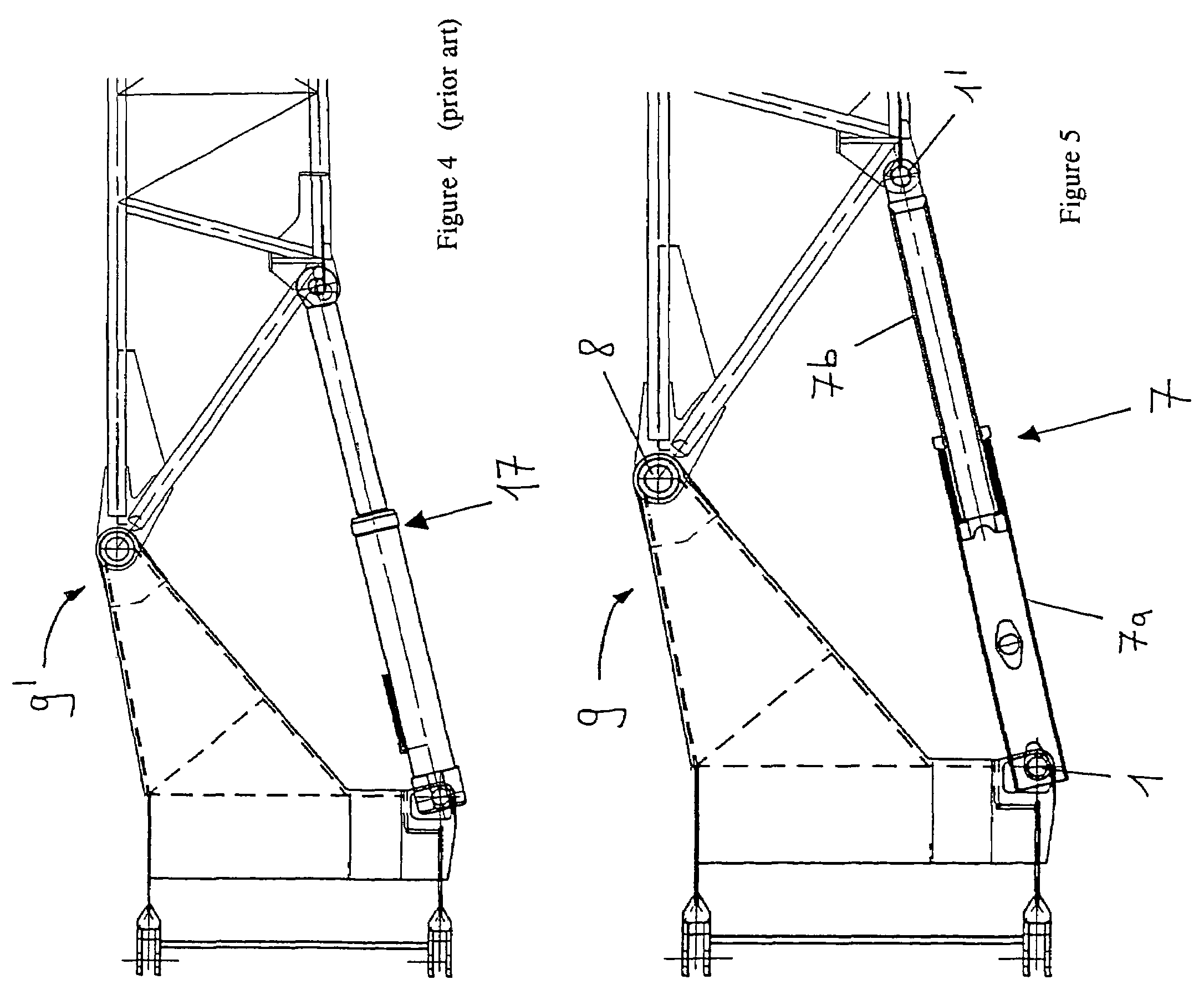
[0022]In FIGS. 4 and 5, the expensive illustration of a bending device comprising a hydraulic cylinder in accordance with the prior art (FIG. 4) is compared with an embodiment in accordance with the invention. FIG. 4 shows the joint area 9′ of the folding pinnacle, wherein a hydraulic cylinder 17 is arranged between two joints on the lower side on which there is a pressure load. In order to simplify said—as explained above—expensive and elaborate embodiment, and to provide a cost-effective alternative, a telescopic pipe 7 is then employed in accordance with the invention (FIG. 5) instead of the hydraulic cylinder. All the remaining components of the folding pinnacle and / or the joint area 9 can continue to be used. The upper portion of the folding pinnacle, running to the right-hand side in FIG. 5, pivots about the joint 8, adjusting an angle which is pre-set by the length of the telescopic pipe 7, the base pipe 7a and extending piston 7b of which are each supported on each other in ...


PUM


Abstract

A folding pinnacle bending device for a mobile crane (20) comprises a joint area (9) which is bent in order to adjust the angle of the folding pinnacle (10) and which comprises a joint (8) in its upper or tensile load area, wherein the joint area (9) comprises a mechanically fixable telescoping means (7) in its lower or pressure load area.

Description

CROSS-REFERENCE TO RELATED APPLICATION[0001]This Nonprovisional application claims priority under 35 U.S.C. § 119(a) on Patent Application No(s). 103 21 493.2 filed in Germany on May 13, 2003, the entire contents of which are hereby incorporated by reference.BACKGROUND OF THE INVENTION[0002]1. Field of the Invention[0003]The present invention relates to a folding pinnacle bending device for a mobile crane. Such folding pinnacles serve as jib extensions on mobile cranes. In order to obtain a greater overhang—for example, over the edges of buildings—for the same size of crane, it is necessary to bend the folding pinnacle. Such an application is shown in the enclosed FIG. 1. In order to be able to operate over the upper edge of the high-rise building 30, the mobile crane 20 bears a folding pinnacle 10 which is fastened to its outermost section and can be bent by means of a bending device 9, such that an overhang over the edge of the building is made possible.[0004]2. Description of Rel...

Claims


Application Information

Patent Timeline
Patent Type & Authority Patents(United States)
IPC IPC(8): B66C23/42B66C23/70
CPCB66C23/702
Inventor HINRICHS, JANSTUHRWOLDT, DIETER
Owner MANITOWOC CRANE GROUP FRANCE
Why Eureka
Try Eureka