Vertical shaft alignment tool

a technology of vertical shaft and tool, which is applied in the direction of mechanical measuring arrangement, instruments, and using mechanical means, etc., can solve the problems of requiring a lot of user training, dated methods and tools are slow and awkward to use, and achieve the effect of reducing the wear on the bearings of equipment, reducing the bearing life, and reducing the bearing load

Inactive Publication Date: 2006-06-01
TENNESSEE VALLEY AUTHORITY
View PDF11 Cites 80 Cited by
  • Summary
  • Abstract
  • Description
  • Claims
  • Application Information

AI Technical Summary

Benefits of technology

[0005] A purpose of this invention is to align a vertical shaft's axis or center of rotation with the earth's gravitational pull (i.e., to plumb the shaft) and to measure the shaft's throw (shaft run out) as the shaft is rotated. The invention was designed primarily to align the vertical generator/turbine shafts in hydroelectric units; however, it is fully capable of aligning vertical shafts in pumps and similar equipment. It is important to align...

Problems solved by technology

These dated methods and tools tend to be slow and awkward to use.
The conventional 4 plumb wire method is a workable method; however, it is very time...

Method used


Image

  • Vertical shaft alignment tool
  • Vertical shaft alignment tool
  • Vertical shaft alignment tool

Examples


Embodiment Construction

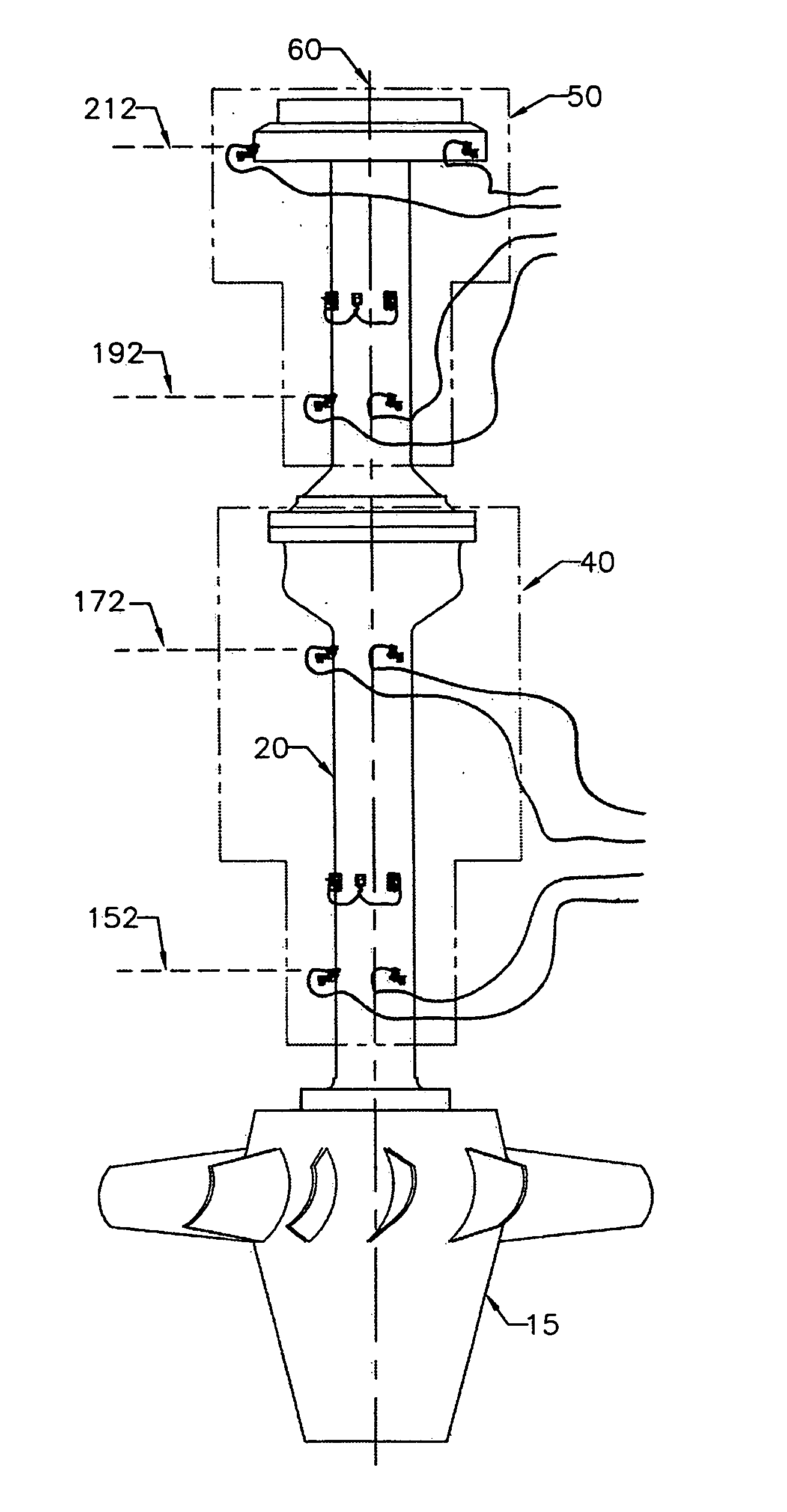
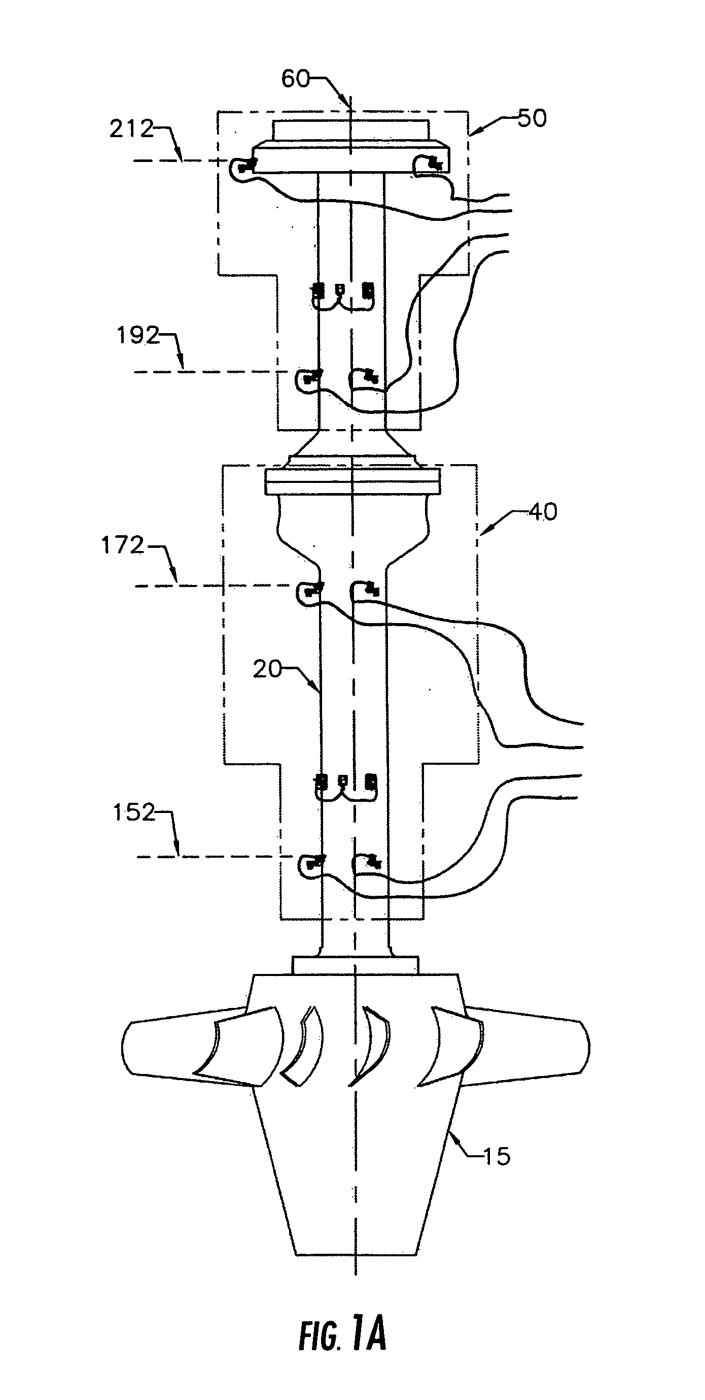
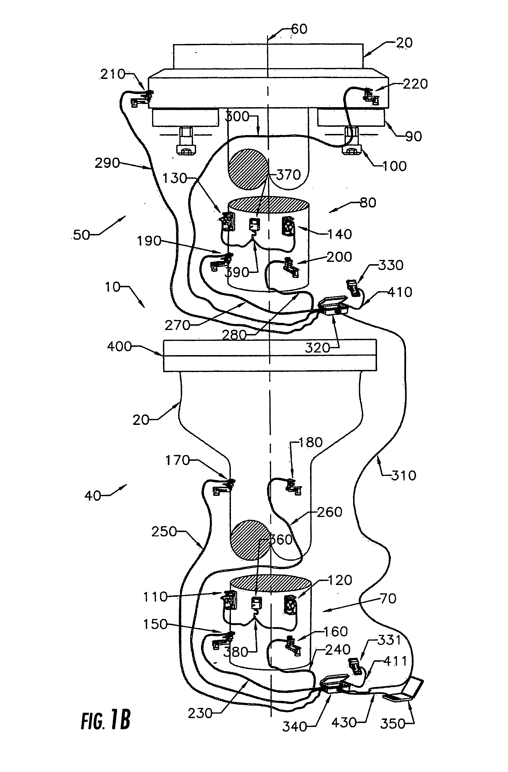
[0050] FIGS. 1(a) and 1(b) are overall perspective views of the vertical shaft alignment tool 10 as assembled on a vertical rotating shaft of a shaft 20, which is comprised of two shaft sections (lower and upper) 40, 50 coupled together. A turbine runner 15 (FIG. 1(a)) is attached at the end of the lower portion of the shaft 20. Although a turbine shafting system is shown, the vertical shaft alignment tool 10 will function with any vertical shaft system, such as, vertical pumps and others. FIG. 1(b) shows the vertical shaft 20 in two expanded sections, the lower shaft section 40 and the upper shaft section 50, with the vertical shaft alignment tool 10 components attached. The normal shaft centerline 60 is shown passing through the center of the shaft 20. The shaft's vertical thrust load is supported on the thrust bearing assembly 90 and is transmitted to the stationary surrounding structure (not shown) by way of the thrust adjustment screw assembly 100.

[0051] The sensors which meas...


PUM


Abstract

An apparatus and a method for aligning a vertical shaft or multiple axially coupled vertical shafts in a hydroelectric turbine generator or a similar vertical-shaft system, and for providing precise plumb inclination alignment of a vertical rotating shaft. Precision inclinometers attached to the vertical shaft measure plumb inclination. Proximity probe displacement devices mounted externally of the vertical shaft measure radial movement, throw, or run out at various shaft elevations as the shaft is rotated relative to a fixed point. Data acquisition devices and communication devices accumulate and transmit alignment data to a micro-computer which receives and processes such data. Methods of defining shaft plumb inclination in a static single rotational position and defining plumb inclination of the virtual centerline of a shaft's rotational throw position. A method of swinging, tilting, or adjusting a vertical shaft to a corrected or different plumb position relative to the earth's gravity.

Description

FIELD OF INVENTION [0001] The present invention relates generally to the alignment of vertical shafts and, more particularly, to aligning a vertical shaft to the plumb position, and to measurement of the built in throw (run out) of a shaft as the shaft is rotated. The present invention also relates to a method and an apparatus for aligning a vertical shaft, or a plurality of axially coupled vertical shafts, of a hydroelectric turbine generator or of a similar vertical-shaft system. [0002] Vertical shafts (particularly hydroelectric generator / turbine shafts) have been aligned using various methods for over 100 years. The most common method (industry standard) is called the 4 plumb wire method. To check the plumb or verticality of a shaft, 4 music wires (or piano wires) are connected to a bracket at an upper elevation and at 4 equally spaced locations, 90 degrees apart, around the shaft. These wires are connected at the bottom to large plumb bobs (usually fifty pound weights) which ar...

Claims


Application Information

Patent Timeline
IPC IPC(8): G01C9/06
CPCG01C9/06G01C15/10
Inventor JONES, JEFFERY CARL
Owner TENNESSEE VALLEY AUTHORITY
Why Eureka
Try Eureka