
Roller bearing

a roller bearing and roller bearing technology, applied in the field of roller bearings, can solve the problems of creep phenomenon, relative rotation therebetween, creep phenomenon of inner ring rotating with respect to shaft, etc., and achieve the effect of increasing the static load rating, increasing the rigidity and reducing the deformation of the inner ring due to the passing of rolling elements

Active Publication Date: 2013-12-19
NSK LTD
View PDF11 Cites 2 Cited by
  • Summary
  • Abstract
  • Description
  • Claims
  • Application Information

AI Technical Summary

Benefits of technology

The present invention relates to a roller bearing with improved load capacity and reduced deformation. The technical effects achieved include an increased ratio between the inner ring and tapered roller, a decreased ratio between the pitch circle diameter and cross-sectional center diameter, and a decreased ratio between the length of the tapered roller and diameter of the tapered roller. These ratios lead to increased static load rating, decreased elastic deformation of the inner ring, and suppression of creep. Additionally, increasing the number of tapered rollers while decreasing the distance between them reduces deformation of the inner ring and suppresses creep. The load on each tapered roller is decreased, and the surface pressure on the inner ring raceway is reduced. The size of the pillars of the cage is decreased, and the distance between the rollers is reduced. The tapered rollers are made closer to each other, canceling out elongations on the inner ring raceway and suppressing creep. The bearing life can be made equal to or more than that of conventional taper roller bearings.

Problems solved by technology

In this kind of taper roller bearing, the outer ring is usually press-fitted into a housing with an interference and secured thereto, and the inner ring is secured to a shaft member with a very small clearance or an interference to prevent relative rotation therebetween; however, a creep phenomenon may occur in which the relative rotation therebetween is caused, for example, due to the change in load associated with the movement of the rolling elements.
Hence, each time each rolling element passes, the inner ring repeatedly expands and contracts in the circumferential direction, thereby causing a creep phenomenon in which the inner ring rotates with respect to the shaft.
If this creep phenomenon is generated, wear occurs on the surface of the shaft, and abrasion powder on the surface gets into the bearing, thereby causing premature flaking.

Method used


Image

  • Roller bearing
  • Roller bearing
  • Roller bearing

Examples


first embodiment

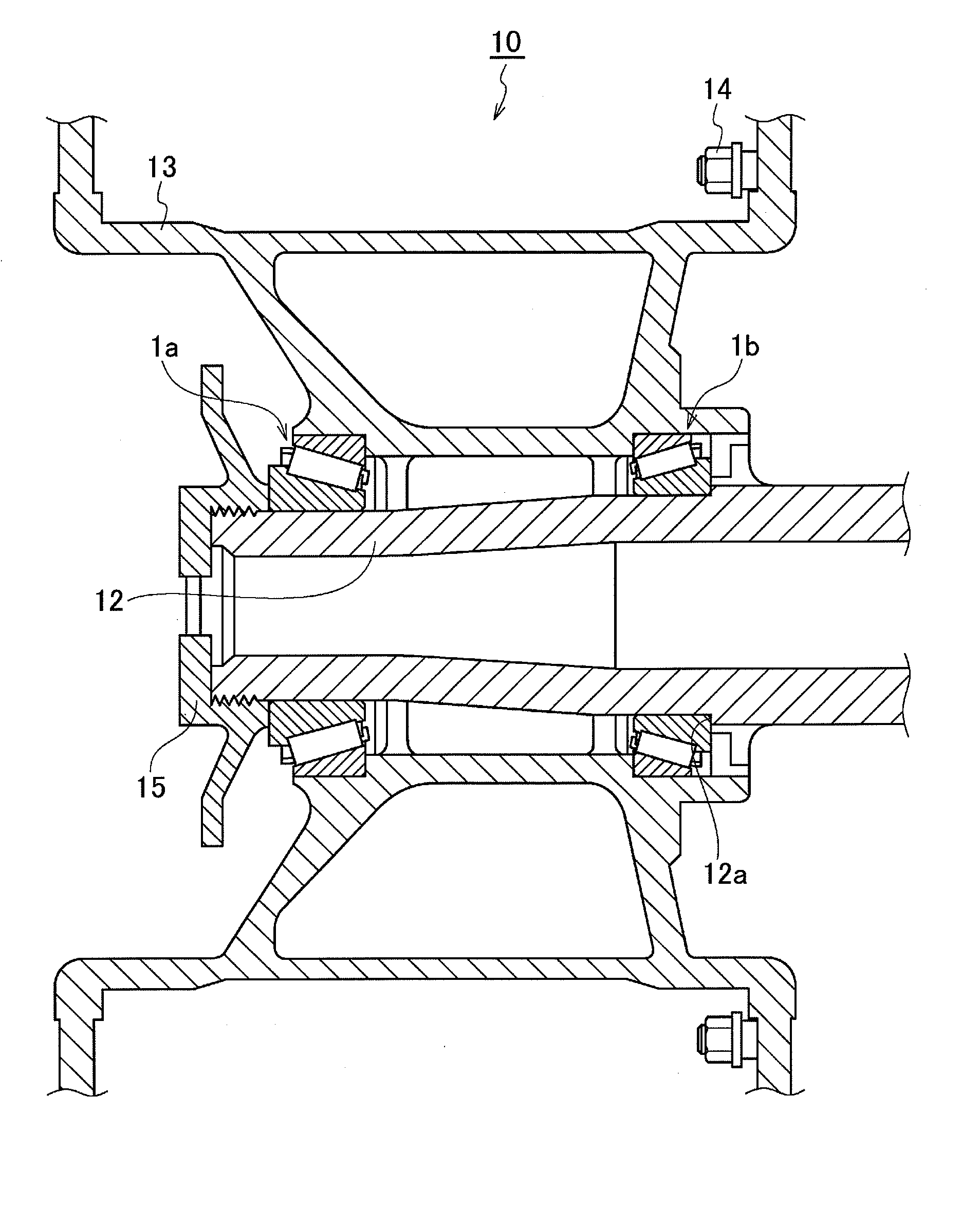
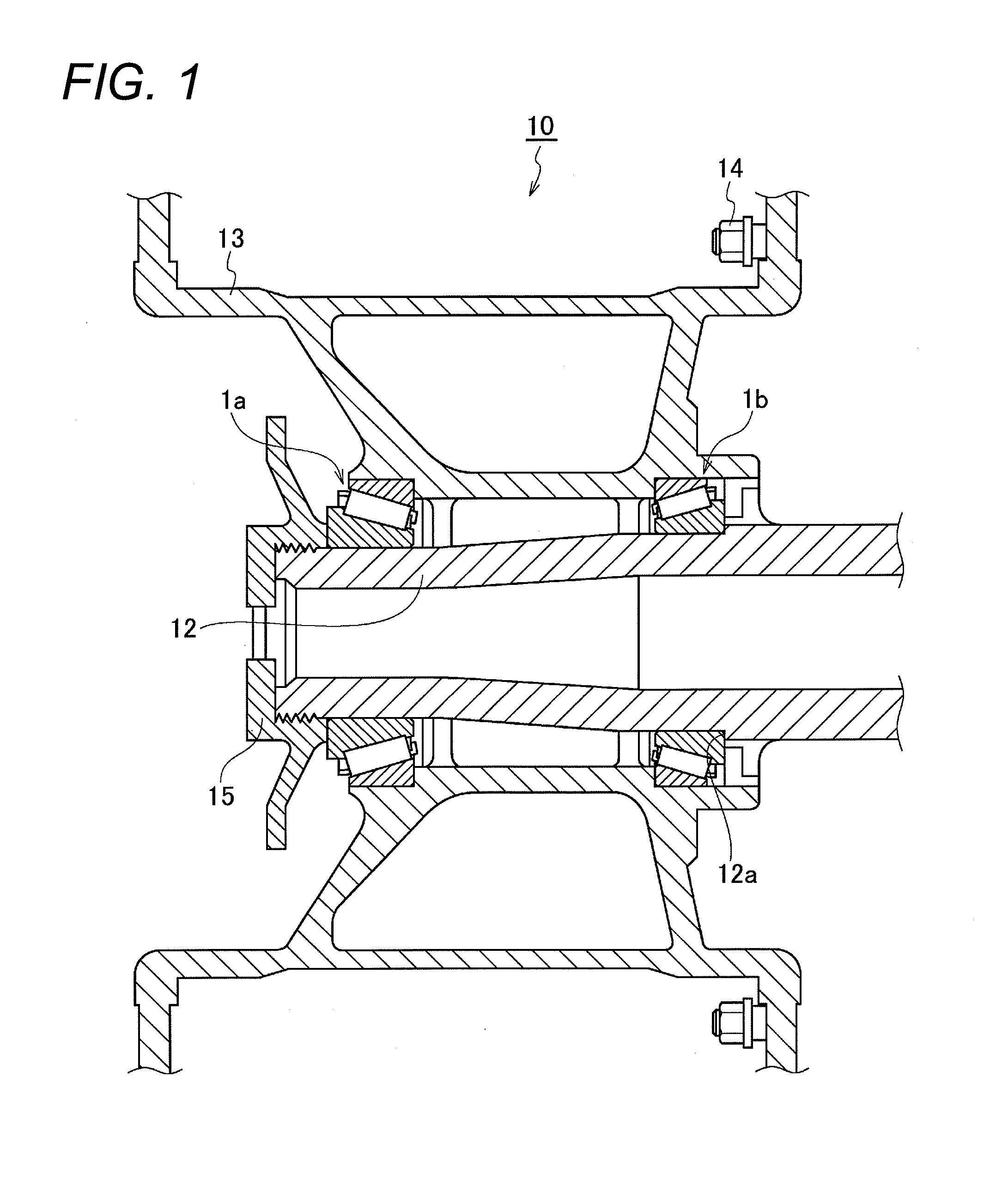
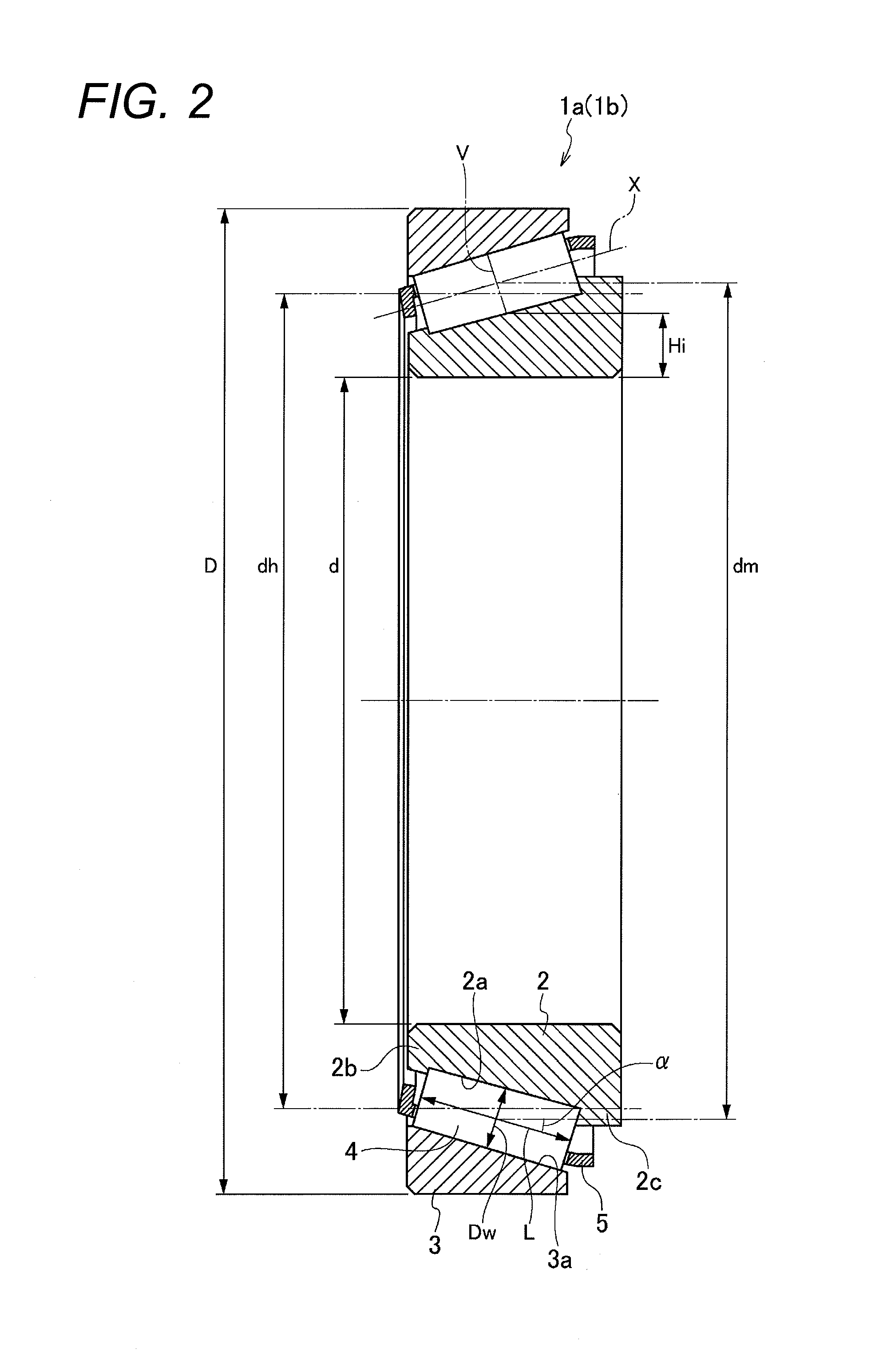
[0082]FIG. 1 is a cross-sectional view showing a case in which taper roller bearings according to a first embodiment of the present invention are applied to a wheel support apparatus, and FIG. 2 is an axially cross-sectional view showing the taper roller bearing, and FIG. 3 is a fragmentary cross-sectional view showing the taper roller bearing in the direction orthogonal to the axis thereof.

[0083]In a wheel support apparatus 10, a pair of taper roller bearings 1a and 1b is disposed between the outer peripheral surface of a shaft member 12 and the inner peripheral surface of a housing 13. The brake drum (not shown) of a braking apparatus and the wheel disc (not shown) of a wheel are installed on the housing 13 using stud bolts 14.

[0084]As shown in FIGS. 1 and 2, each of the taper roller bearings 1a and 1b is equipped with an inner ring 2, an outer ring 3, a plurality of tapered rollers 4, and a cage 5. The inner ring 2 has a tapered inner ring raceway 2a on the outer peripheral surfa...

second embodiment

[0097]In the first embodiment described above, the metallic cage integrally formed by press-molding is used as an example; however, in a second embodiment, the end face shape of the tapered roller and the configuration of the cage are different from those of the taper roller bearing according to the first embodiment, and the other configurations are identical or equivalent to those of the taper roller bearing according to the first embodiment. Although the taper roller bearing according to the second embodiment is described below, the components identical or equivalent to those of the taper roller bearing according to the first embodiment are designated by identical or equivalent reference codes and their descriptions are omitted.

[0098]As shown in FIG. 4A, a taper roller bearing 11 is equipped with an inner ring 2, an outer ring 3, a plurality of tapered rollers 4A, and a cage 5A. The inner ring 2 has a tapered inner ring raceway 2a on the outer peripheral surface thereof and has a ...

third embodiment

[0103]In the first and second embodiments described above, taper roller bearings are taken as examples of roller bearings being used for outer-ring rotation in the wheels of heavy dump trucks, mine / construction dump trucks, wheel loaders, etc.; however, the present invention is also applicable to cylindrical roller bearings being used for outer-ring rotation in planetary gears for general industrial machinery, etc. In the second embodiment, a cylindrical roller bearing will be described.

[0104]As shown in FIG. 6A, a cylindrical roller bearing 21 is equipped with an inner ring 22, an outer ring 23, a plurality of cylindrical rollers 24, and a cage 25. The inner ring 22 has an inner ring raceway 22a on the outer peripheral surface thereof, and the outer ring 23 has an outer ring raceway 23a on the inner peripheral surface thereof, and rib sections 23b and 23c on both sides of the outer ring raceway 23a. The plurality of tapered rollers 24 are rotatably provided between the inner ring r...


PUM


Abstract

A tapered roller bearing (1a, 1b) satisfies the following three conditions: (a1) 0.8≦Hi / Dw≦1.2, (b1) 1.01≦dm / dh≦1.05, and (c1) 2.1≦L / Dw≦3.0, where a pitch circle diameter at a center of a roller length along an axis line (X) of each tapered roller (4) is (dm), the radial dimension of the inner ring (2) at an intersection of the inner ring raceway (2a) and a perpendicular line (v) extending from a position of the pitch circle diameter in a direction perpendicular to the axis line is the thickness (Hi) of the inner ring, a cross-sectional center diameter of the roller bearing is (dh), the length of the tapered roller (4) is the length (L) of the tapered roller, and a half of the sum of the large diameter dimension and the small diameter dimension of the tapered roller (4) is the diameter (Dw) of the tapered roller.

Description

TECHNICAL FIELD[0001]The present invention relates to a roller bearing, and more particularly, to a roller bearing being used for outer-ring rotation in the wheels of heavy dump trucks, mine / construction dump trucks, wheel loaders, etc., and in planetary gears for general industrial machinery, etc.BACKGROUND ART[0002]Conventionally, as roller bearings for ratably supporting the wheels of a heavy vehicle on the suspension system thereof, taper roller bearings having a large load capacity and high rigidity have been used favorably. In this kind of taper roller bearing, the outer ring is usually press-fitted into a housing with an interference and secured thereto, and the inner ring is secured to a shaft member with a very small clearance or an interference to prevent relative rotation therebetween; however, a creep phenomenon may occur in which the relative rotation therebetween is caused, for example, due to the change in load associated with the movement of the rolling elements. In ...

Claims


Application Information

Patent Timeline
Patent Type & Authority Applications(United States)
IPC IPC(8): F16C33/36
CPCB60B35/02F16C19/386F16C25/08F16C33/36F16C2240/70F16C2240/80F16C33/366F16C19/26F16C19/364F16C19/38F16C19/548F16C23/086F16C2361/61F16C2326/02
Inventor KANDA, YUTAKA
Owner NSK LTD
Learn More