

Cross spherical roller bearing
A technology of spherical rollers and bearings, applied in the field of crossed roller bearings, which can solve problems such as unusable and limited bearing limit speed
- Summary
- Abstract
- Description
- Claims
- Application Information
AI Technical Summary
Problems solved by technology
Method used
Image

Examples
Embodiment Construction
[0024] Exemplary embodiments of the present invention are described below with reference to the accompanying drawings. It should be understood that these specific descriptions are only used to teach those skilled in the art how to implement the present invention, but are not intended to exhaust all possible ways of the present invention, nor are they intended to limit the scope of the present invention.
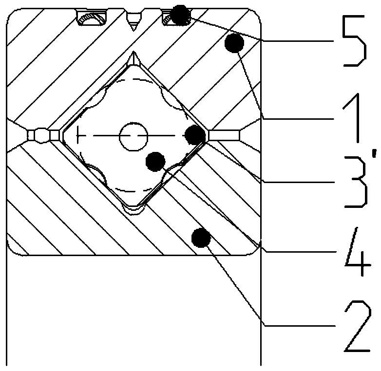
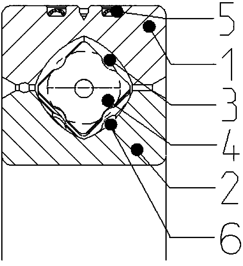
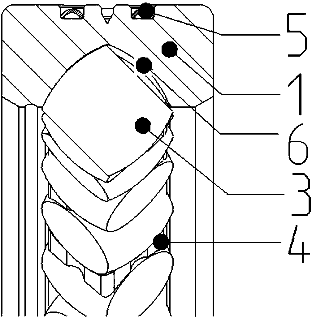
[0025] figure 2 is a sectional view of a crossed spherical roller bearing according to an embodiment of the present invention. Such as figure 2 As shown, the crossed spherical roller bearing is composed of outer ring 1, inner ring 2, spherical rollers (hereinafter also referred to as rolling elements) 3, spacer blocks 4 and lock rings 5. The rolling elements 3 are spaced and guided by spacer blocks 4 . The inner ring 2 is designed in one piece. The outer ring 1 has two halves in the circumferential direction. After the rolling elements 3 and the spacer blocks 4 are asse...
PUM
 Abstract
Description
Claims
Application Information