

Multi-chamber container and cap therefor
- Summary
- Abstract
- Description
- Claims
- Application Information
AI Technical Summary
Benefits of technology
Problems solved by technology
Method used
Image

Examples
first embodiment
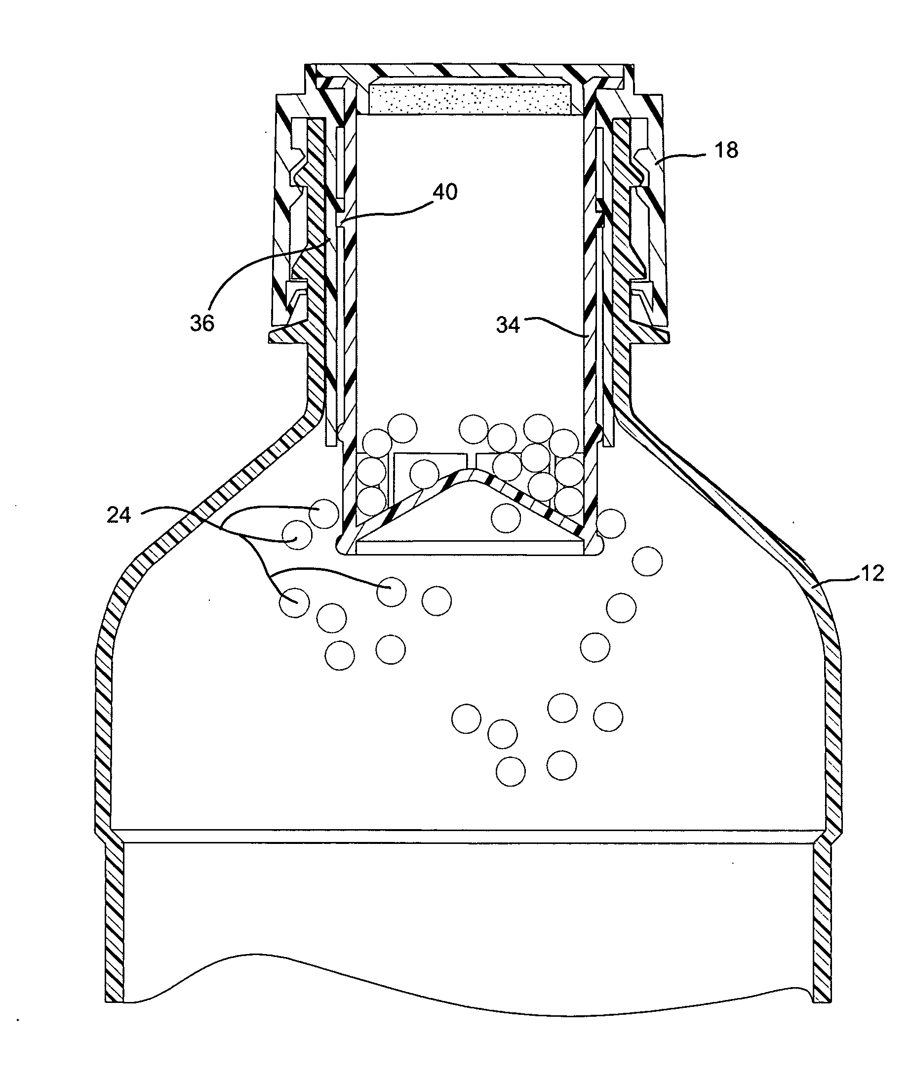
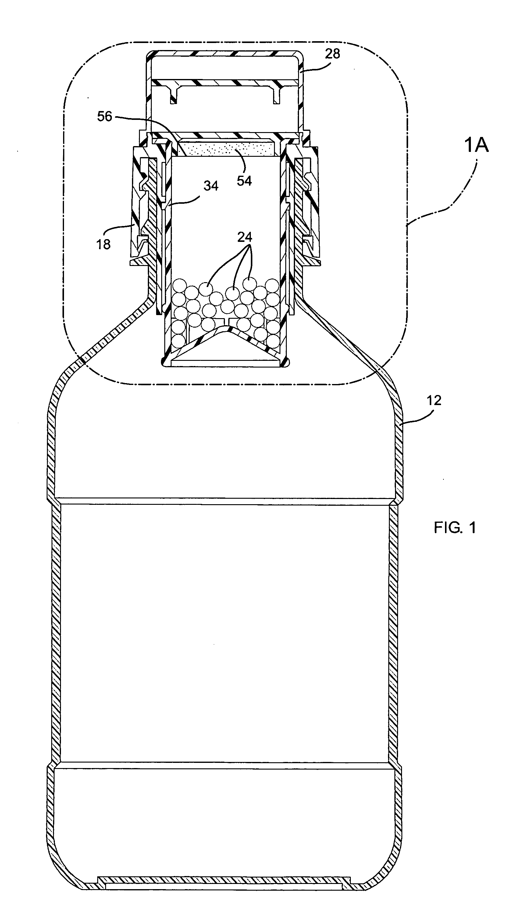
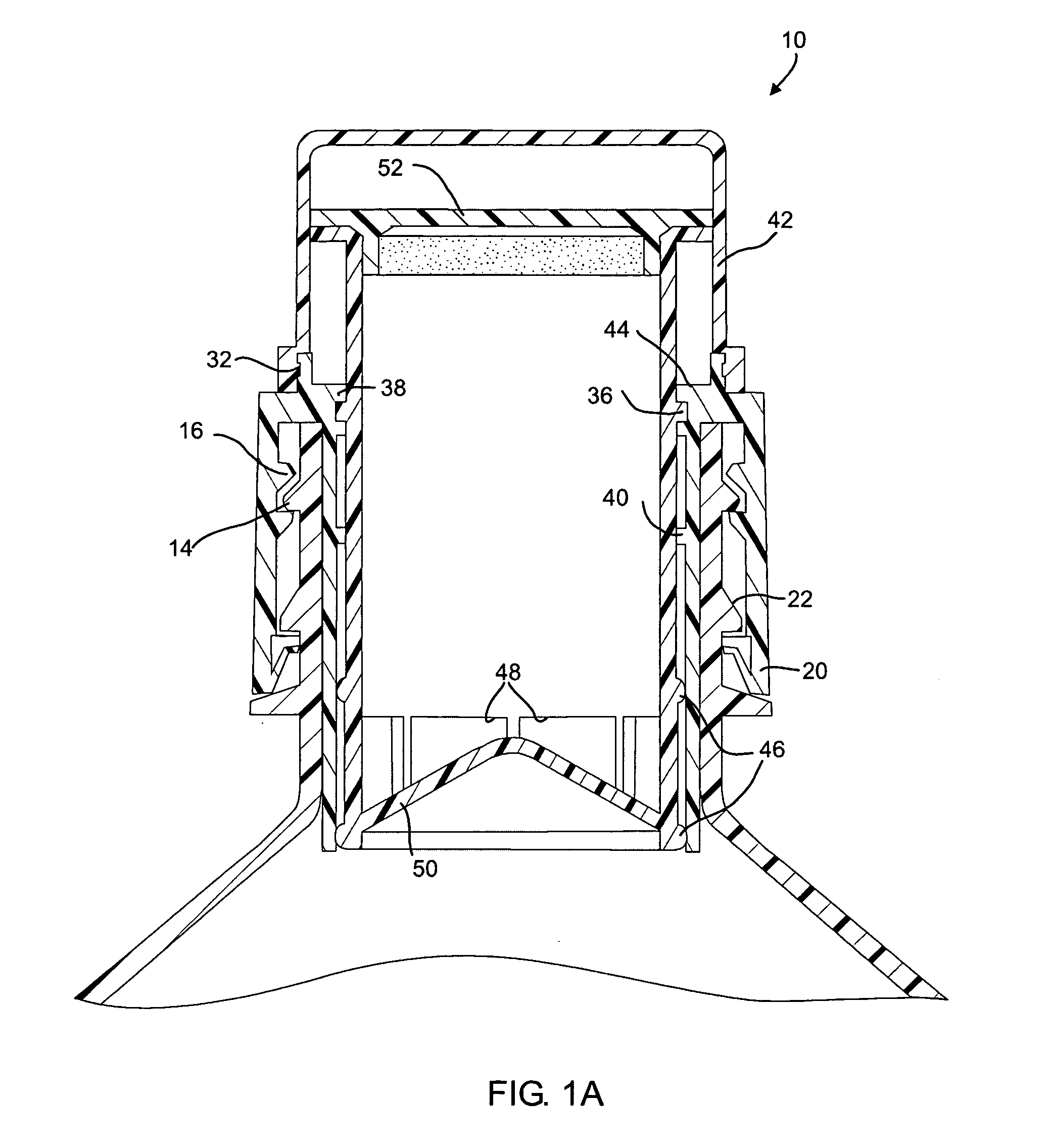
[0042] the invention is depicted with respect to FIGS. 1-4B. In FIG. 1, the dispensing closure or cap 10 is shown in use with a plastic container 12 which contains a main component such as water or a variety of different fluids. The container 12 or main package has a threaded neck 14 to which the dispensing closure 10 is mounted using internal threads 16, FIG. 4, included in the container cap or body 18. The container cap 18 or cap is serrated 80, (FIG. 4), in order to facilitate the assembly and disassembly of the dispensing closure 10 to the container 12.
[0043] The container cap 18 is provided with a tamper proof ring 20 that locks behind a collar 22 built into the container neck 14, when the dispensing closure 10 is threaded all the way in. When removing the dispensing closure 10 after the first component 24 has been added to the container 12, the tamper proof ring 20 remains locked behind the collar 22 and the unscrewing motion provides enough force to break thin protrusions 26F...
second embodiment
[0076] In an embodiment, the invention may include a pull cap (with or without sipper). This embodiment of the invention is similar to the first aforementioned two preferred embodiments, except that the dispensing of the first component into the supplemental component motion is reversed and a pull action is used instead of push. Removing the protective cap and pulling a plug up above the narrow part of a funnel shaped first component holder, allows the first component to be dispensed into the main package. this alternate version provides a liquid dispensing nozzle or sipper that allows utilization of the mixed components without removing the closure from the main package.
third embodiment
[0077] Turning to FIGS. 8-13, the present invention is depicted. A container main body 100 forms a first chamber 101. In an embodiment, the container main body 100 may have the shape of well-known isotonic beverage or energy drink bottles and may be manufactured according to well-known methods of manufacturing such bottles. In an embodiment, the container main body 100 may be formed of a PET material and is filled by a room temperature or cooler fill process. The container main body 100 includes an opening 104 formed by a neck 106. In a preferred embodiment, the neck 106 is threaded.
[0078] A container cap 110 is mounted to the neck 106. In the preferred embodiment, the container cap 110 is threaded onto the neck 106. The cap 110 forms a second chamber 112 (see FIG. 11) that stores a component. In a preferred embodiment, the second chamber provides an air-tight seal to protect the component and allows the cap 110 or container 100 to be stored on a shelf without degradation or spoilag...
PUM
 Abstract
Description
Claims
Application Information