System for dynamically determining vehicle rear/trunk loading for use in a vehicle control system

a technology for dynamically determining vehicle rear/trunk loading and vehicle control, which is applied in the direction of pedestrian/occupant safety arrangement, anti-theft devices, instruments, etc., can solve the problem that relatively small mass change may significantly affect the directional dynamics of the vehicl

a technology for dynamically determining vehicle rear/trunk loading and vehicle control, which is applied in the direction of pedestrian/occupant safety arrangement, anti-theft devices, instruments, etc., can solve the problem that relatively small mass change may significantly affect the directional dynamics of the vehicl

US20060129291A1Inactive Publication Date: 2006-06-15FORD GLOBAL TECH LLC

Image

  • System for dynamically determining vehicle rear/trunk loading for use in a vehicle control system
  • System for dynamically determining vehicle rear/trunk loading for use in a vehicle control system
  • System for dynamically determining vehicle rear/trunk loading for use in a vehicle control system

Examples


Embodiment Construction

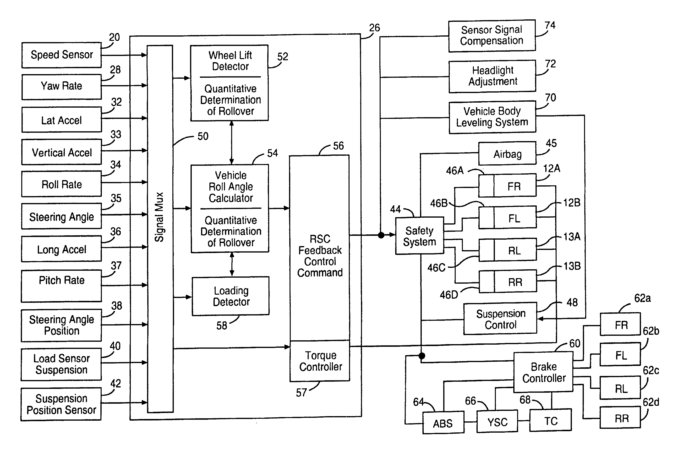
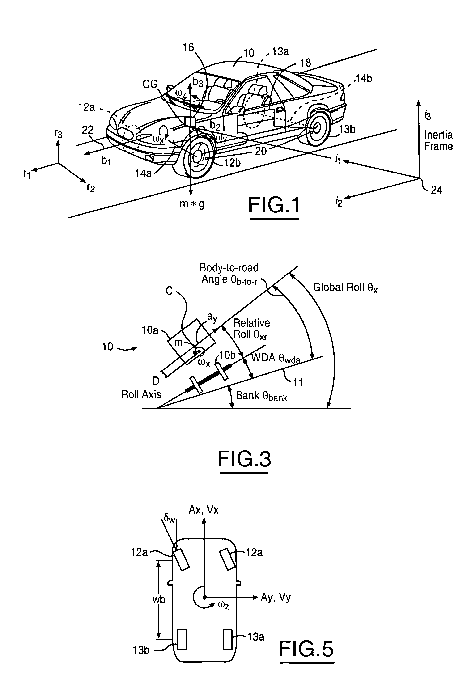
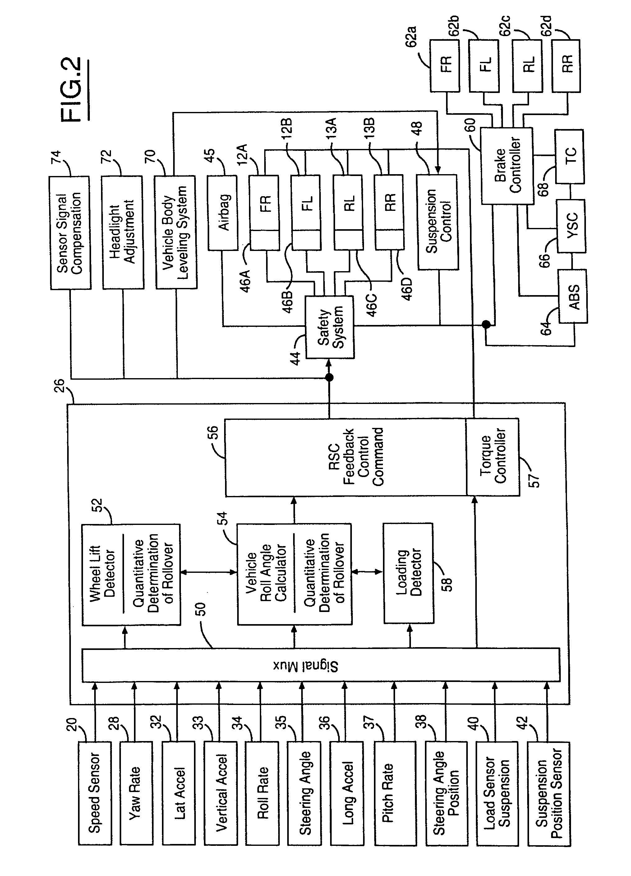
[0019] In the following figures, the same reference numerals will be used to identify the same components. The present invention may be used in conjunction with a rollover control system for a vehicle. The present invention may also be used with a deployment device such as airbag or active roll bar or pre-tensioning belts. The present invention could pass information to an adaptive cruise control system or a brake based collision avoidance system to change the brake request levels of the system. The present invention will be discussed below in terms of preferred embodiments relating to an automotive vehicle moving in a three-dimensional road terrain. The present invention is described with respect to determining an added mass and position of the added mass. However, as will be described below the added mass and position may not be directly determined, rather by adaptively updating a pitch condition parameter such as a pitch gradient value and / or a pitch acceleration coefficient, the...


PUM


Abstract

A control system (18) and method for an automotive vehicle (10) includes a pitch rate sensor (37) generating a pitch rate signal, a longitudinal acceleration sensor (36) generating a longitudinal acceleration signal, and a yaw rate sensor (28) generating a yaw rate signal. A safety system (44) and the sensors are coupled to a controller. From the sensors, the controller (26) determines an added mass and a position of the added mass, a pitch gradient and / or a pitch acceleration coefficient that takes into account the added mass and position. The controller controls a vehicle system in response to the added mass and the position of the added mass, the pitch gradient and / or pitch acceleration coefficient variables.

Description

TECHNICAL FIELD [0001] The present invention relates generally to a control apparatus for controlling a system of an automotive vehicle in response to sensed dynamic behavior, and more specifically, to a method and apparatus for determining a rear vehicle loading and and / or the impact of vehicle loading on the control apparatus of the vehicle. BACKGROUND [0002] Recently, vehicle roll stability control (RSC) schemes, i.e., U.S. Pat. No. 6,324,446, have been proposed to address the issue of friction-induced rollovers. RSC system includes a variety of sensors sensing vehicle states and a controller that controls a distributed brake pressure to reduce a tire force so the net moment of the vehicle is counter to the roll direction. [0003] During an event causing the vehicle to roll, the vehicle body is subject to a roll moment due to the coupling of the lateral tire force and the lateral acceleration applied to the center of gravity of vehicle body. This roll moment causes suspension heig...

Claims


Application Information

Patent Timeline
15 Jun 2006
Publication
US20060129291A1
IPC
G06F19/00
CPC
B60T8/17554; B60W30/04; B60W40/072; B60W40/076; B60W40/13; B60W2520/14; B60W2520/16; B60W2720/16
Inventors
LU, JIANBO; MATTSON, KEITH