Check patentability & draft patents in minutes with Patsnap Eureka AI!

Ultra-wideband dipole antenna

a dipole antenna and ultra-wideband technology, applied in the field of antennas, can solve the problems that the prior dipole antenna does not meet the requirements of multiple frequency bands or ultra-wideband applications, and achieve the effects of increasing the diameter, increasing the impedance matching of the antenna, and increasing the operating frequency

Active Publication Date: 2006-06-29
ADVANCED CONNECTEK INC
View PDF5 Cites 7 Cited by
  • Summary
  • Abstract
  • Description
  • Claims
  • Application Information

AI Technical Summary

Benefits of technology

The ultra-wideband dipole antenna significantly increases operating frequency without height increase, achieving a bandwidth of 9.6 GHz within a 3:1 VSWR impedance bandwidth, making it suitable for high-speed wireless transmission of image and large data in multiple frequency band applications.

Problems solved by technology

As such, the prior dipole antenna does not meet the requirements for multiple frequency band or ultra-wideband applications.

Method used


Image

  • Ultra-wideband dipole antenna
  • Ultra-wideband dipole antenna
  • Ultra-wideband dipole antenna

Examples


Embodiment Construction

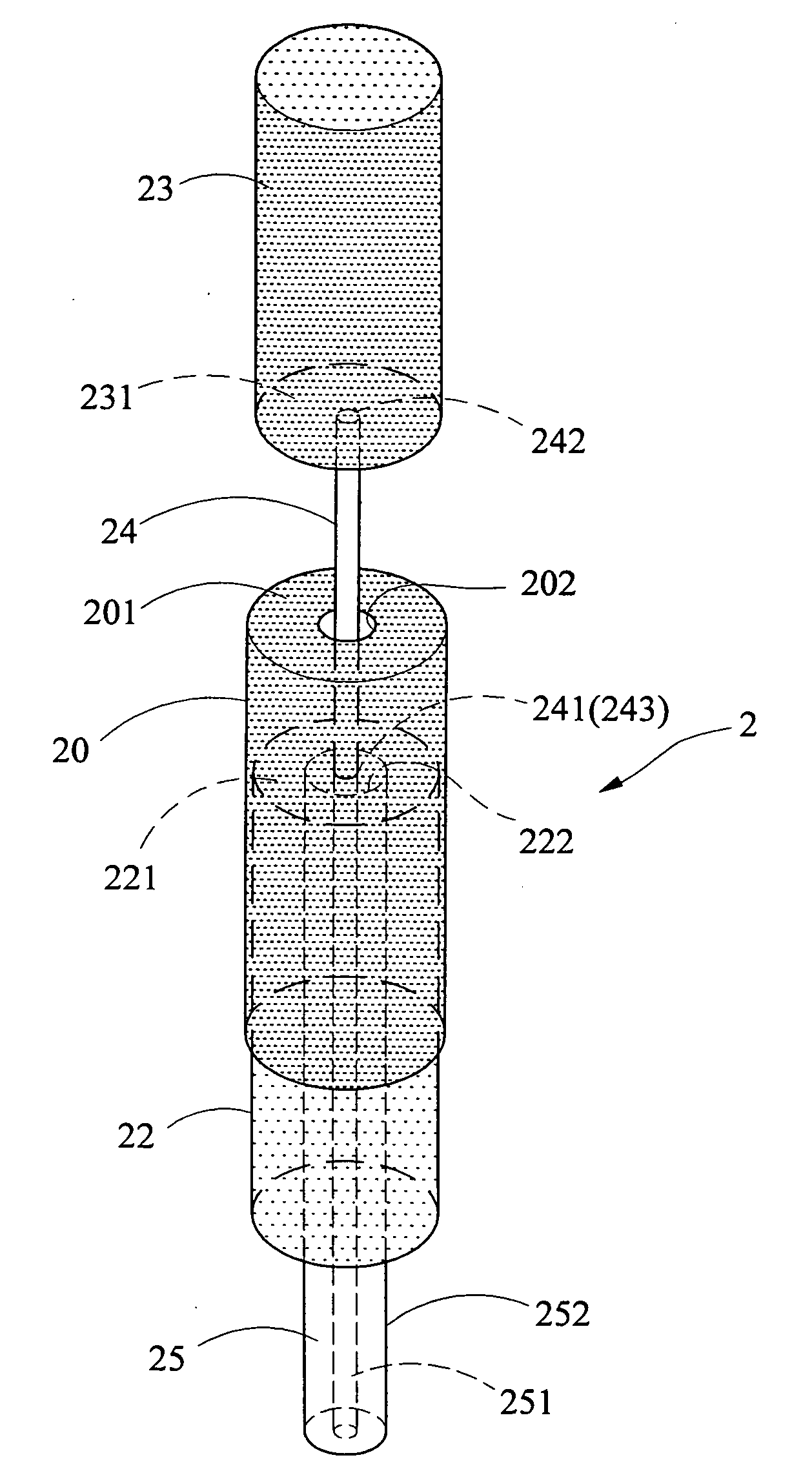
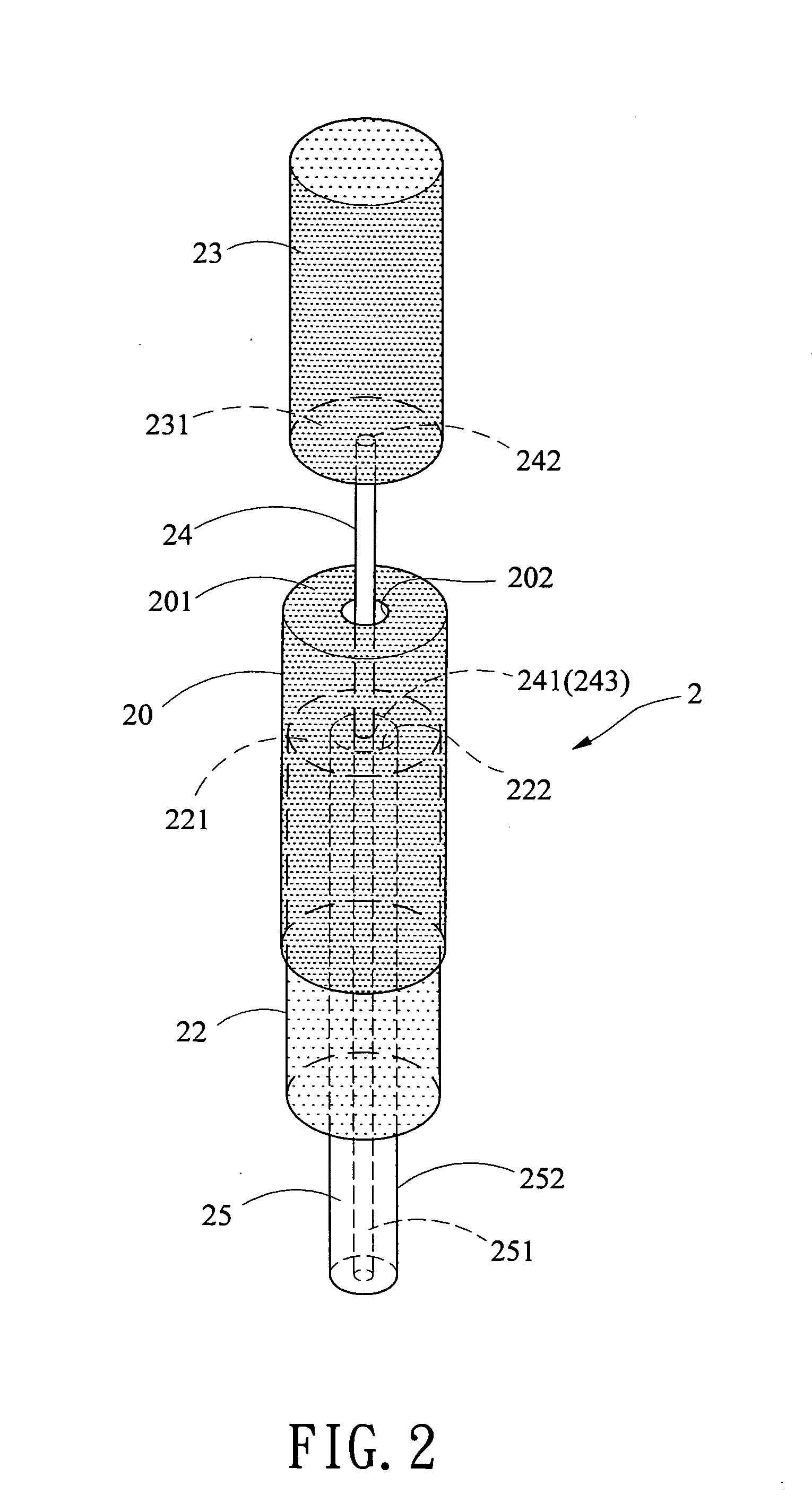
[0017] Referring to FIGS. 2 and 3, there is shown an ultra-wideband dipole antenna 2 in accordance with a first preferred embodiment of the invention comprising a generally axially disposed first outer metal sleeve 20 having a closed face 201 at a top end thereof opposite its open bottom end, and a hole 202 through the closed face 201; a generally axially disposed intermediate metal sleeve 22 dimensioned to be surrounded by the first outer metal sleeve 20, the intermediate metal sleeve 22 having a closed face 221 at a top end thereof opposite its open bottom end, and a hole 222 through the closed face 221; a generally axially disposed second outer metal sleeve 23 above the first outer metal sleeve 20, the second outer metal sleeve 23 having a closed face 231 at a bottom end thereof opposite its open top end; a conductive interconnection 24 having a bottom end 241 extended through the hole 202, a feed point location 243 at the bottom end 241, and a top end 242 electrically connected ...


PUM


Abstract

Provided is an ultra-wideband dipole antenna. In one embodiment, the antenna comprises a first outer sleeve, an intermediate sleeve surrounded by the first outer sleeve, a second outer sleeve above the first outer sleeve, a conductive interconnection interconnected the outer sleeves, and an inner coaxial conductor surrounded by the intermediate sleeve. A distance between the first outer sleeve and the intermediate sleeve can be changed for adjusting the generated capacitance for obtaining a required impedance matching in the resonance mode of an antenna operating bandwidth and an ultra-wideband characteristic. The antenna is particularly suitable for operating in a frequency range of 2.1 GHz to 11.7 GHz.

Description

BACKGROUND OF THE INVENTION [0001] 1. Field of Invention [0002] The present invention relates to antennas and more particularly to an improved ultra-wideband dipole antenna mounted in a wireless communication device (e.g., cellular phone or PDA). [0003] 2. Description of Related Art [0004] Wireless communication has known a rapid, spectacular development in recent years. Also, requirements for quality and performance of antenna mounted in a wireless communication device (e.g., cellular phone or PDA) are increased. In addition to the requirement of miniature antenna, multiple frequency band or ultra-wideband feature is also necessary. For many types of newly developed wireless communication devices, having an ultra-wideband antenna is critical for high speed wireless transmission of image data or large amount of data. [0005] A conventional dipole antenna is shown in FIG. 1 and comprises an inner metal conductor 13 having a feed point location 131 at one end thereof, a coaxial conduct...

Claims


Application Information

Patent Timeline
Patent Type & Authority Applications(United States)
IPC IPC(8): H01Q9/16H01Q1/24H01Q5/00H01Q5/357H01Q9/22H01Q9/28
CPCH01Q1/242H01Q5/357H01Q9/22
Inventor LIN, SHENG-CHIHCHIU, TSUNG-WENBAI, YUN-FANHSIAO, FU-REN
Owner ADVANCED CONNECTEK INC
Features
  • R&D
  • Intellectual Property
  • Life Sciences
  • Materials
  • Tech Scout
  • Unparalleled Data Quality
  • Higher Quality Content
  • 60% Fewer Hallucinations
Learn More