Routing method and network structure

a routing method and network structure technology, applied in the direction of digital transmission, data switching networks, electrical devices, etc., can solve problems such as inability to solve problems, and require costly software updating

a routing method and network structure technology, applied in the direction of digital transmission, data switching networks, electrical devices, etc., can solve problems such as inability to solve problems, and require costly software updating

US20060176872A1Inactive Publication Date: 2006-08-10NOKIA SOLUTIONS & NETWORKS OY

Image

  • Routing method and network structure
  • Routing method and network structure
  • Routing method and network structure

Examples


Embodiment Construction

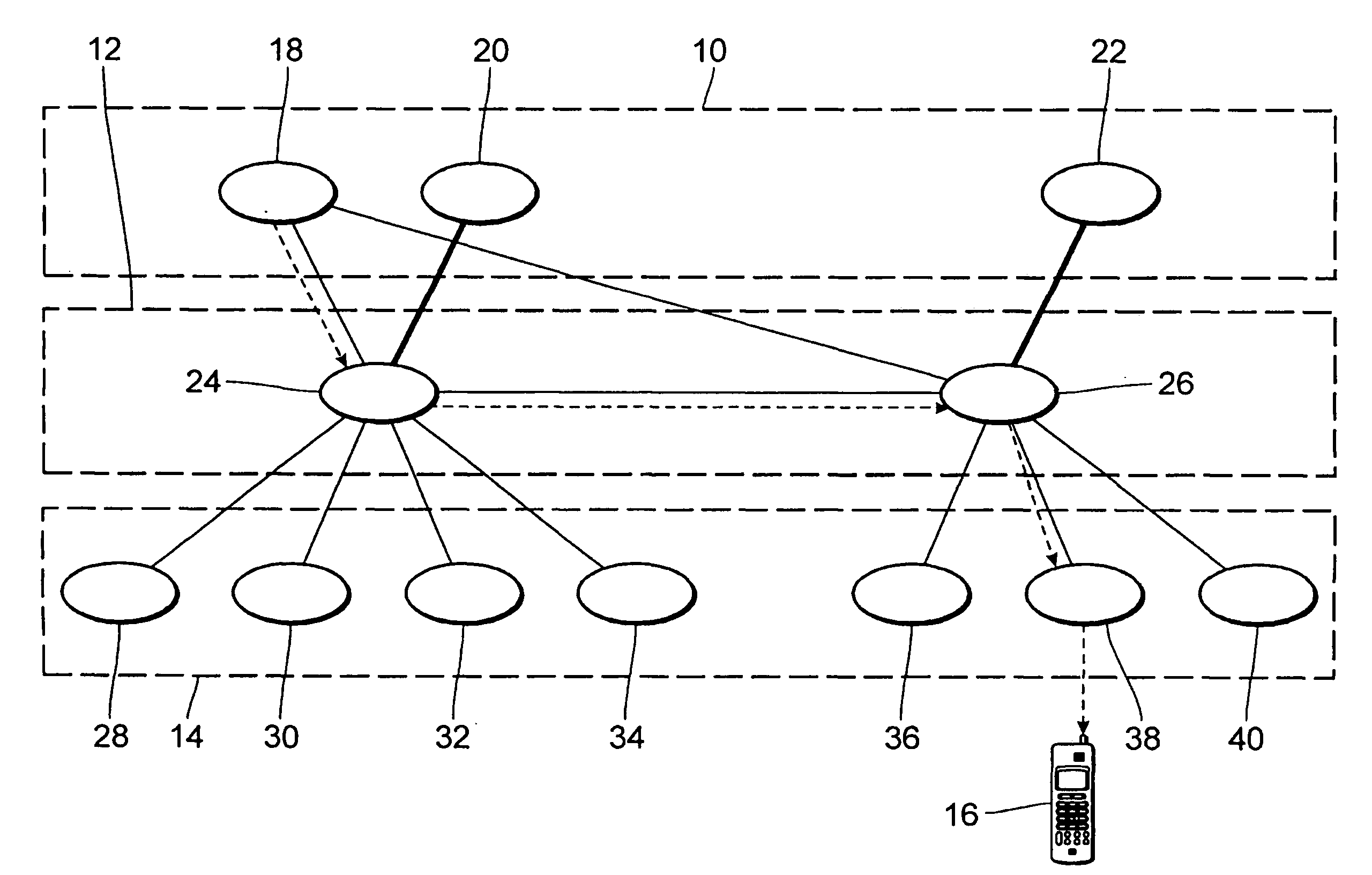
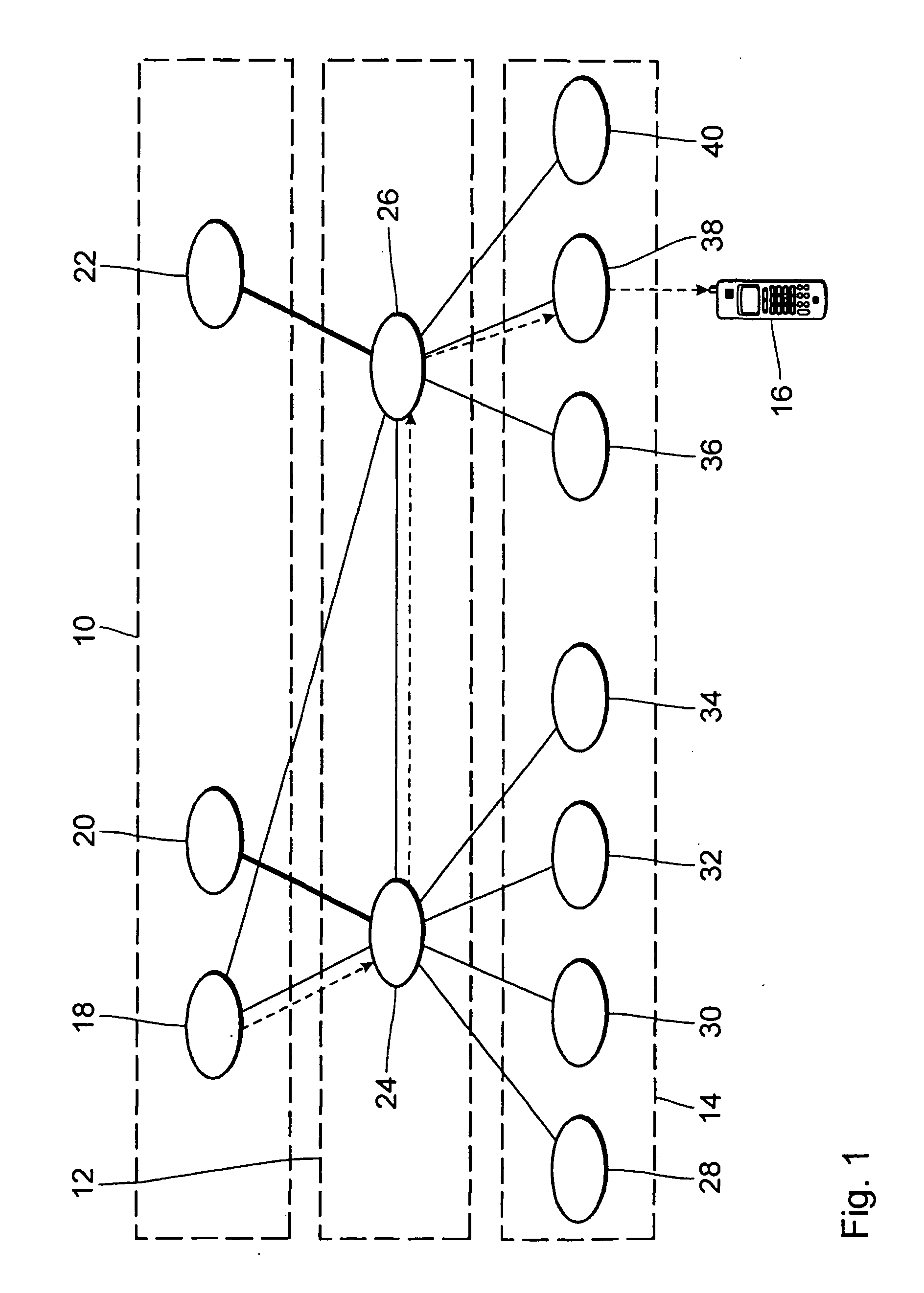
[0067] A first preferred embodiment will now be described on the basis of a network structure according to FIG. 1.

[0068] The network structure of FIG. 1 has a core network 10, a radio access network (RAN) 12 of GERAN (e.g., GERAN release 5 or higher) type, and a GERAN Registration area (GRA) 14 to which a mobile station (MS) 16 is attached. GRA 14 will in the following also be addressed by the more general term Radio Registration Area (RRA).

[0069] Core network 10 comprises an MSC 18 and a first a second SGSN 20 and 22, respectively. It is noted that CN 10 may comprise additional network nodes; which are omitted in FIG. 1 for reasons of simplicity. MSC 18 controls the CS-domain connections for MS 16. MSC 18 provides a digital exchange able to perform all necessary functions needed to handle calls to and from mobile station 16, such as registration, authentication, location updating, and handovers. Specifically, MSC 18 provides the call handling necessary to cope with the mobile nat...


PUM


Abstract

The present invention relates to a method and network system for changing a routing path between a first data network and a mobile station attached to a second data network. The said first data network comprises at least one first network node. The second data network comprises at least a second network node and a third network node. The routing path comprises before said change said first network node, said second network node and said third network node, and after said change said first network node, and said third network node. According to the method of the invention the method comprises a step of transferring an information element from said second network node to said third network node, wherein said information element comprises an identification element of said first network node. The method is preferably used for routing of paging response messages to International Mobile Subscriber Identity (IMSI) paging request messages in a GSM / EDGE Radio Access Network (GERAN) or Universal Terrestrial Radio Access Network (UTRAN) that supports Iuflex functionality.

Description

FIELD OF THE INVENTION [0001] The present invention relates to a routing method and to a data network system. It also relates to a network device for operation in a radio data network. BACKGROUND OF THE INVENTION [0002] Modern radio data networks evolve towards network architectures that support packet-switched (PS) services and the Internet Protocol (IP) in all instances from the mobile station to the core network. However, circuit-switched (CS) services will have to be supported as well since most subscribers use equipment that works according to previous CS standards like GSM. [0003] Currently developing third generation project partnership (3GPP) communication network standards support both PS and CS data services. Their architecture and location and mobility management will be shortly reviewed in the following. This will lead to the problem underlying the present invention. [0004] a) General Network Architecture [0005] A network according to these standards comprises a core net...

Claims


Application Information

Patent Timeline
10 Aug 2006
Publication
US20060176872A1
IPC
H04L12/28; H04L12/56; H04W8/24; H04W40/36; H04W68/12; H04W92/02
CPC
H04W8/24; H04W40/36; H04W68/12; H04W92/02
Inventors
SERNA, PEDRO; LONGONI, FABIO