System and method of detecting fluid and leaks in thermal treatment system basins

US20060194324A1Inactive Publication Date: 2006-08-31MICROTEK MEDICAL

Image

  • System and method of detecting fluid and leaks in thermal treatment system basins
  • System and method of detecting fluid and leaks in thermal treatment system basins
  • System and method of detecting fluid and leaks in thermal treatment system basins

Examples


Embodiment Construction

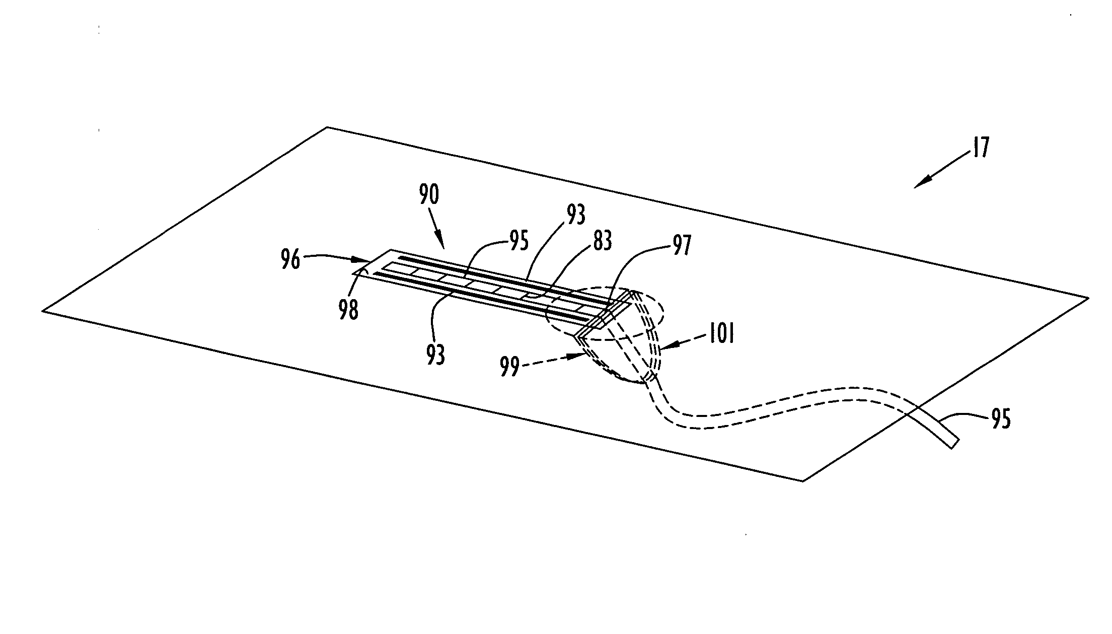
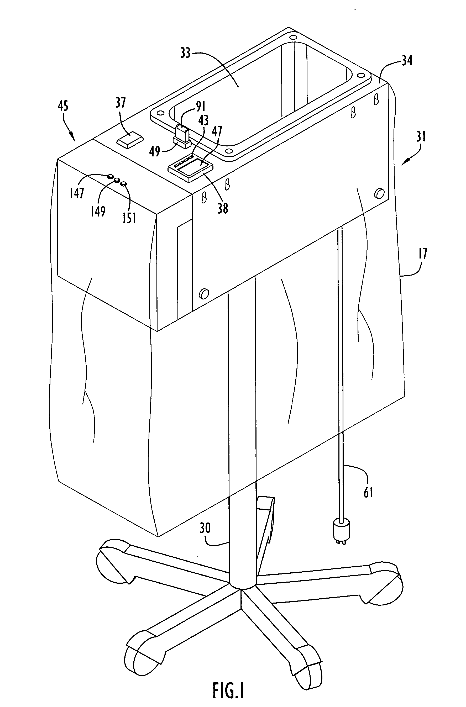
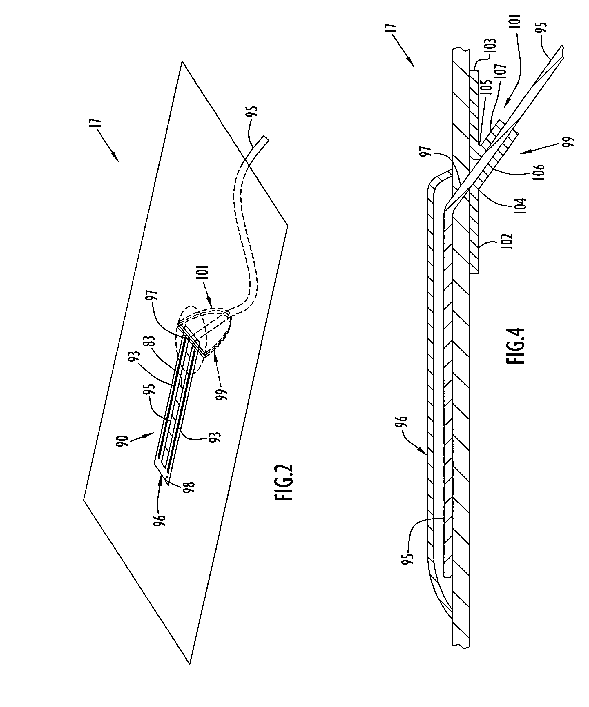
[0035] An exemplary thermal treatment system and drape to heat a sterile medium (e.g., solution or liquid) and detect drape container conditions according to the present invention is illustrated in FIG. 1. Specifically, the system includes a cabinet or housing 31, a wiring housing 45 attached to the cabinet and a warming basin 33 recessed into a cabinet top surface 34. The cabinet or housing may be disposed on a stand 30, preferably including casters or rollers for transport, or be utilized on a table or counter top. Basin 33 may be of any shape; however, by way of example only, the basin is illustrated as being substantially rectangular. A power switch 37 and a temperature controller / indicator 38 are provided on top surface 34 adjacent basin 33 and toward wiring housing 45. The wiring housing is attached to the cabinet side wall that is closest to power switch 37 and facilitates connections as described below. A receptacle 49 is disposed on top surface 34 between the power switch a...


PUM


Abstract

A drape including a sensing device according to the present invention is disposed over a top surface of a thermal treatment system having a basin recessed therein. A portion of the drape is pushed down into the basin to form a drape container for collecting a sterile medium. The thermal treatment system may be of the type that either heats or congeals the sterile medium. The sensing device includes electrodes that are typically disposed through the drape and sealed. The electrodes provide signals indicating the presence of liquid and / or leaks or other conditions within the drape container to the system to facilitate control of system operation. In addition, the sensing device includes a fuse to limit the drape to a single use. The system disables the fuse to indicate prior use and detects tampering to bypass the fuse, thereby preventing use of the drape for subsequent medical procedures.

Description

CROSS-REFERENCE TO RELATED APPLICATIONS [0001] This application is: a continuation-in-part of U.S. patent application Ser. No. 10 / 172,731, entitled ā€œMethod and Apparatus for Ensuring Sterility of Disposable Medical Items Used with Medical Equipmentā€ and filed Jun. 17, 2002; and a continuation-in-part of U.S. patent application Ser. No. 10 / 836,236, entitled ā€œSurgical Drape with Conductor and Method of Detecting Fluid and Leaks in Thermal Treatment System Basinsā€ and filed May 3, 2004, which is a continuation-in-part of U.S. patent application Ser. No. 10 / 372,674, entitled ā€œMedical Solution Thermal Treatment System and Method of Controlling System Operation in Accordance with Detection of Solution and Leaks in Surgical Drape Containersā€ and filed Feb. 25, 2003, now U.S. Pat. No. 6,910,485, which is a continuation-in-part of U.S. patent application Ser. No. 09 / 983,021, entitled ā€œMedical Solution Thermal Treatment System and Method of Controlling System Operation in Accordance with Dete...

Claims


Application Information

Patent Timeline
31 Aug 2006
Publication
US20060194324A1
IPC
G01N31/22
CPC
A61B19/081; A61B2017/0023; A61B2019/025; A61B2019/4873; A61F7/0085; G01N31/226; A61B50/13; A61B46/10
Inventors
FARIES, DURWARD I. JR.; HEYMANN, BRUCE R.