Light emitting diode (LED) driver

a technology of light-emitting diodes and drivers, applied in the direction of identification means, instruments, recording apparatus, etc., can solve the problems of adversely affecting the stability of electromagnetic interference (emi) and the stability of the circuit, and lowering the light efficiency, so as to achieve excellent circuit stability and high light efficiency

Inactive Publication Date: 2006-09-07
SAMSUNG ELECTRONICS CO LTD
View PDF6 Cites 42 Cited by
  • Summary
  • Abstract
  • Description
  • Claims
  • Application Information

AI Technical Summary

Benefits of technology

[0018] Accordingly, it is an aspect of the present invention to substantially solve the above and other problems, and provide an LED driver which has high light efficiency and excellent circuit stability without electromagnetic interference (EMI).

Problems solved by technology

However, if the inductance is raised, the transient phenomenon becomes slow, thereby lowering the light efficiency.
However, a reverse recovery current of the second diode 284 generated while changing the divergence switch may adversely affect stability of electromagnetic interference (EMI) and stability of the circuit.
Further, the DMD module is turned off until the reverse recovery current disappears and the circuit is stabilized, thereby lowering the light efficiency.

Method used


Image

  • Light emitting diode (LED) driver
  • Light emitting diode (LED) driver
  • Light emitting diode (LED) driver

Examples


Embodiment Construction

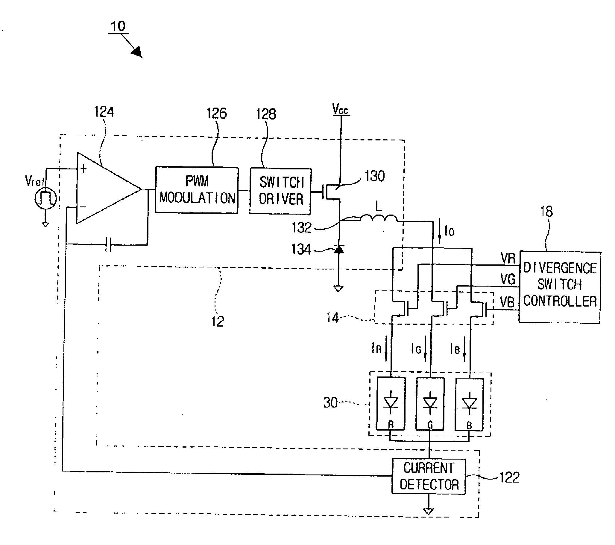
[0033] Reference will now be made in detail to embodiments of the present invention, examples of which are illustrated in the accompanying drawings, wherein like reference numerals refer to like elements throughout. The embodiments are described below in order to explain the present invention by referring to the figures. FIG. 4 illustrates a configuration of an LED driver 10 according to an exemplary embodiment of the present invention.

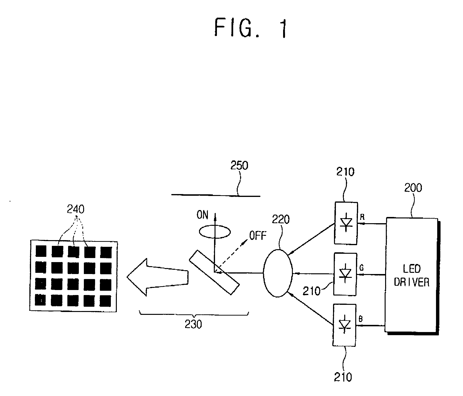
[0034] The LED driver 10 of the embodiment drives a plurality of LEDs 30 which are used as a light source of a digital micromirror device (DMD) display apparatus, such as a digital light processing (DLP) projection TV, projector, and the like, using the DMD, and an LCD back light.

[0035] As shown in FIG. 4, the LED driver 10 comprises a current controller 12, a plurality of divergence switches 14, and a divergence switch controller 18. The plurality of divergence switches 14 of the embodiment are disposed between the current controller 12 and an anod...


PUM


Abstract

An LED driver is provided for driving a plurality of light emitting diodes (LEDs), having a current controller to control a power supply of a predetermined power source unit to establish a current in the plurality of LEDs at a predetermined target current value and which sequentially changes corresponding to the respective LEDs, a plurality of divergence switches to allow flow or interrupt flow of the current with respect to each of the plurality of LEDs, and a divergence switch controller to sequentially open and close the plurality of divergence switches corresponding to changes of the target current value to make one of the plurality of divergence switches turn on before another one of the plurality of divergence switches is turned off. Thus, the LED driver has high light efficiency and excellent circuit stability without electromagnetic interference (EMI).

Description

CROSS-REFERENCE TO RELATED APPLICATIONS [0001] This application claims the benefit under 35 U.S.C. §119(a) of Korean Patent Application No. 10-2005-0016208, filed in the Korean Intellectual Property Office on Feb. 26, 2005, the entire disclosure of which is incorporated herein by reference. BACKGROUND OF THE INVENTION [0002] 1. Field of the Invention [0003] The present invention relates to an LED driver. More particularly, the present invention relates to an LED driver which drives light emitting diodes with high light efficiency and improved circuit stability. [0004] 2. Description of the Related Art [0005] Light emitting diodes (LEDs) are typically used as a light source of a liquid crystal display (LCD) apparatus, as well as a digital micromirror device (DMD) display apparatus such as a digital light processing (DLP) projection TV, projector, and the like, that use a digital micromirror device (DMD). [0006]FIG. 1 illustrates a DMD display apparatus which employs LEDs as the light...

Claims


Application Information

Patent Timeline
Patent Type & Authority Applications(United States)
IPC IPC(8): H05B41/36H05B44/00
CPCH05B33/0815H05B33/0818H05B33/086Y02B20/347H05B45/20Y02B20/30H05B45/3725G01F15/068G09F9/33G01D13/12G01D15/14G01D1/18
Inventor KIM, NAM-IN
Owner SAMSUNG ELECTRONICS CO LTD
Why Eureka
Try Eureka