Recording disk drive

a disk drive and recording technology, applied in the field of disk drives, can solve problems such as damage to the head slider, and achieve the effect of reliably holding the swinging movemen

Inactive Publication Date: 2006-09-28
TOSHIBA STORAGE DEVICE CORP
View PDF7 Cites 4 Cited by
  • Summary
  • Abstract
  • Description
  • Claims
  • Application Information

AI Technical Summary

Benefits of technology

[0008] It is accordingly an object of the present invention to provide a disk dri

Problems solved by technology

There is a possibility that

Method used


Image

  • Recording disk drive
  • Recording disk drive
  • Recording disk drive

Examples


Embodiment Construction

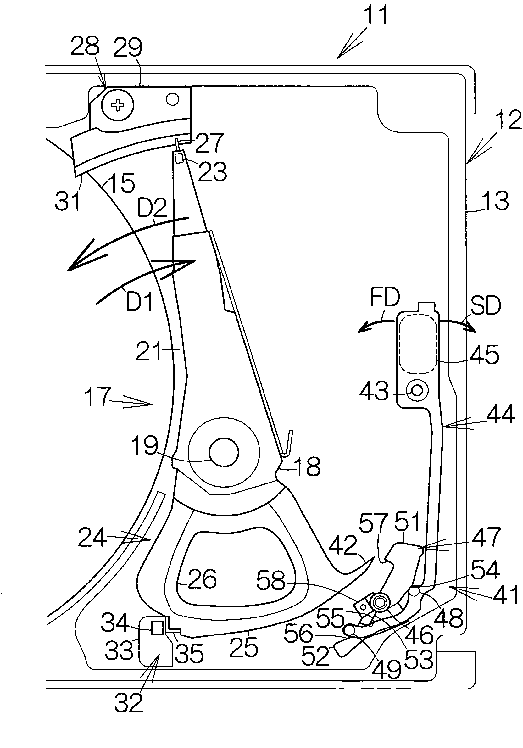
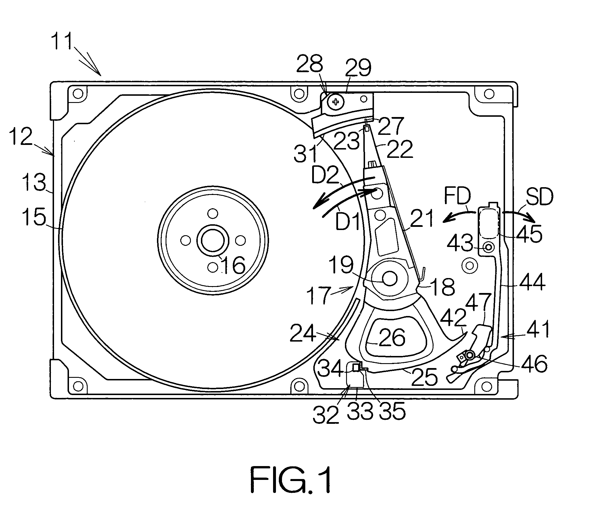
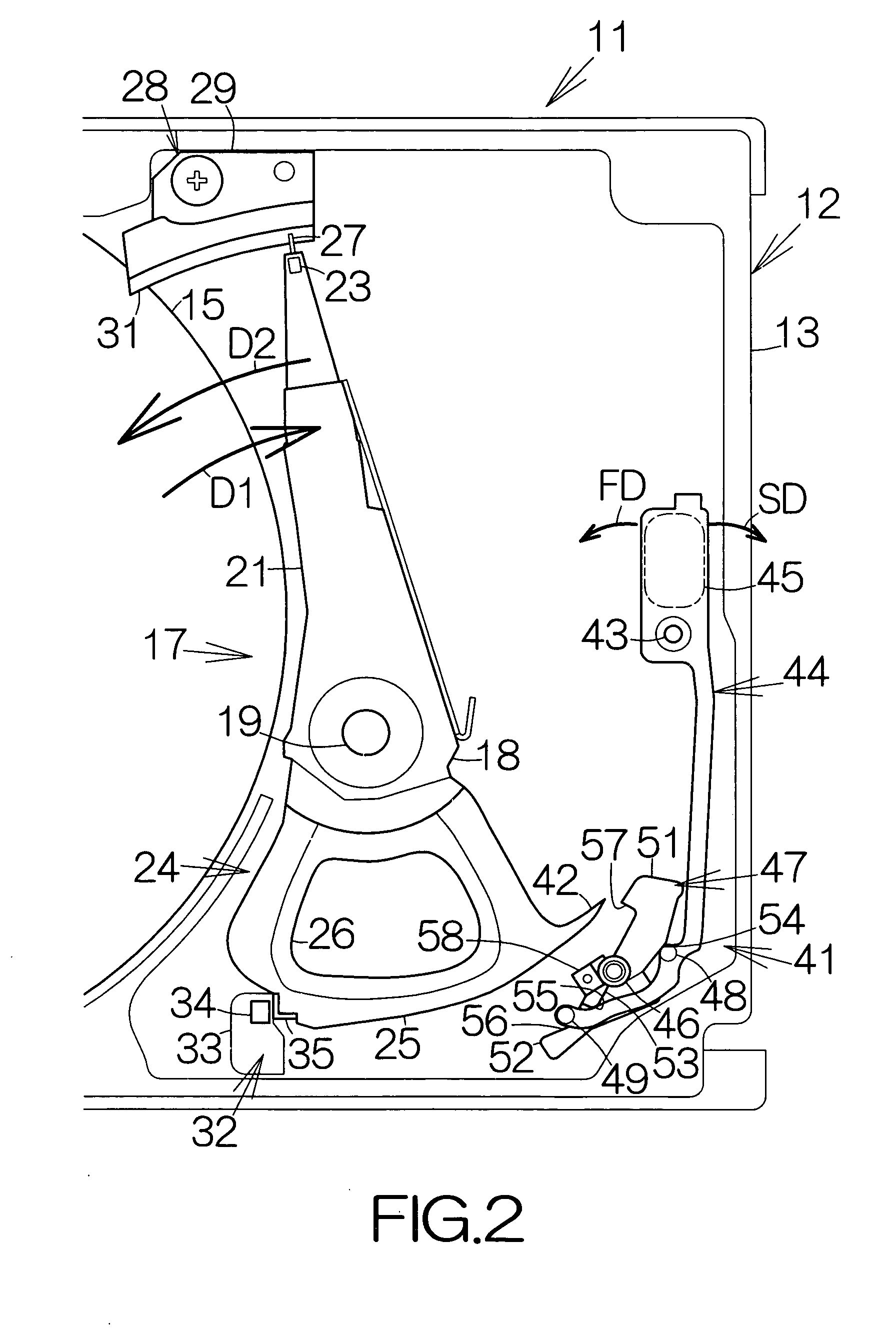
[0020]FIG. 1 schematically illustrates the inner structure of a hard disk drive, HDD, 11 as an example of a recording disk drive or storage device according to an embodiment of the present invention. The hard disk rive 11 includes a box-shaped enclosure 12. The enclosure 12 includes a boxed-shaped base 13 defining an inner space of a flat parallelepiped, for example. The base 13 may be made of a metallic material such as aluminum, for example. Molding process may be employed to form the base 13.

[0021] A cover, not shown, is coupled to the base 13. The cover serves to close the opening of the inner space within the base 13. Pressing process may be employed to form the cover out of a plate material, for example. The plate material may be made of a metallic plate such as an aluminum plate, for example. The plate material may be a layered material, for example.

[0022] At least one magnetic recording disk 15 as a recording media is incorporated within the inner space of the base 13. The...


PUM


Abstract

A lever and a weight are supported on a first shaft for swinging movement in a latch mechanism. The weight gets closer to a head actuator member based on swinging movement in a first direction. A restriction member restricts the swinging movement of the weight in a second direction opposite to the first direction. A swinging member is contacted with the lever swinging around the first shaft so that the swinging member gets into a predetermined path of the head actuator member through the swinging movement around the second shaft. The disk drive always allows the weight, the lever and the swinging member to start swinging from corresponding inoperative positions, even if the disk drive suffers from a sequential driving force in opposite directions due to impact. A head slider at the tip end of the head actuator member is reliably prevented from colliding against the disk.

Description

BACKGROUND OF THE INVENTION [0001] 1. Field of the Invention [0002] The present invention relates to a disk drive such as a hard disk drive (HDD). In particular, the invention relates to a disk drive comprising a disk and a ramp member located at a location outside the disk. [0003] 2. Description of the Prior Art [0004] A head actuator is incorporated in a hard disk drive, for example. The head actuator includes an actuator arm allowed to swing around a support shaft along a predetermined path. When the actuator arm furthest swings in a normal direction outward in the radial direction of the magnetic recording disk, the actuator arm is positioned at the inoperative position. The tip end of the actuator arm is received on a ramp member. When the actuator arm swings from the inoperative position in the reverse direction opposite to the normal direction, the tip end of the actuator arm is released from support of the ramp member. [0005] A so-called latch mechanism is often incorporated...

Claims


Application Information

Patent Timeline
IPC IPC(8): G11B5/54
CPCG11B5/54
Inventor KATO, YASUHIKOARIKAWA, YOSHIHIROAKAMA, KAZUNORI
Owner TOSHIBA STORAGE DEVICE CORP
Why Eureka
Try Eureka