Anterior interbody spinal implant

Active Publication Date: 2006-11-23
TITAN SPINE
View PDF32 Cites 48 Cited by
  • Summary
  • Abstract
  • Description
  • Claims
  • Application Information

AI Technical Summary

Benefits of technology

[0009] The present invention is directed to interbody spinal implants and methods of using same. The interbody spinal implants are particularly suited for placement using an anterior surgical approach. Certain preferred embodiments of the present invention provide for an anatomically shaped spinal implant for improved seating in the disc space, particularly in the medial-lateral aspect of the disc space, and improved utilization of the vertebral apophyseal rim. Certain embodiments of the present invention further hav

Problems solved by technology

Over time, the discs may become diseased, infected, develop deformities such as tears/cracks, or simply lose structural integrity, for example bulge or flatten.
These impaired discs can affect the anatomical functions of the vertebrae, due to the resultant lack of proper biomechanical support, and are often associated with chronic back pain.
The seating of these threaded cylindrical implants may also compromise biomechanical integrity by reducing the area in which to distribute mechanical forces, thus increasing the apparent stress experienced by both the implant and vertebrae.
Still further, a substantial risk of implant subsidence into the softer cancellous bone of the vertebral body may arise from such improper seating.
Traditional ring-shaped cages, however, are generally comprised of allograft bone material, harvested from the human femur, which restrict the usable size and shape of the resultant implant.
As such, these cages may not be o

Method used


Image

  • Anterior interbody spinal implant
  • Anterior interbody spinal implant
  • Anterior interbody spinal implant

Examples


example 1

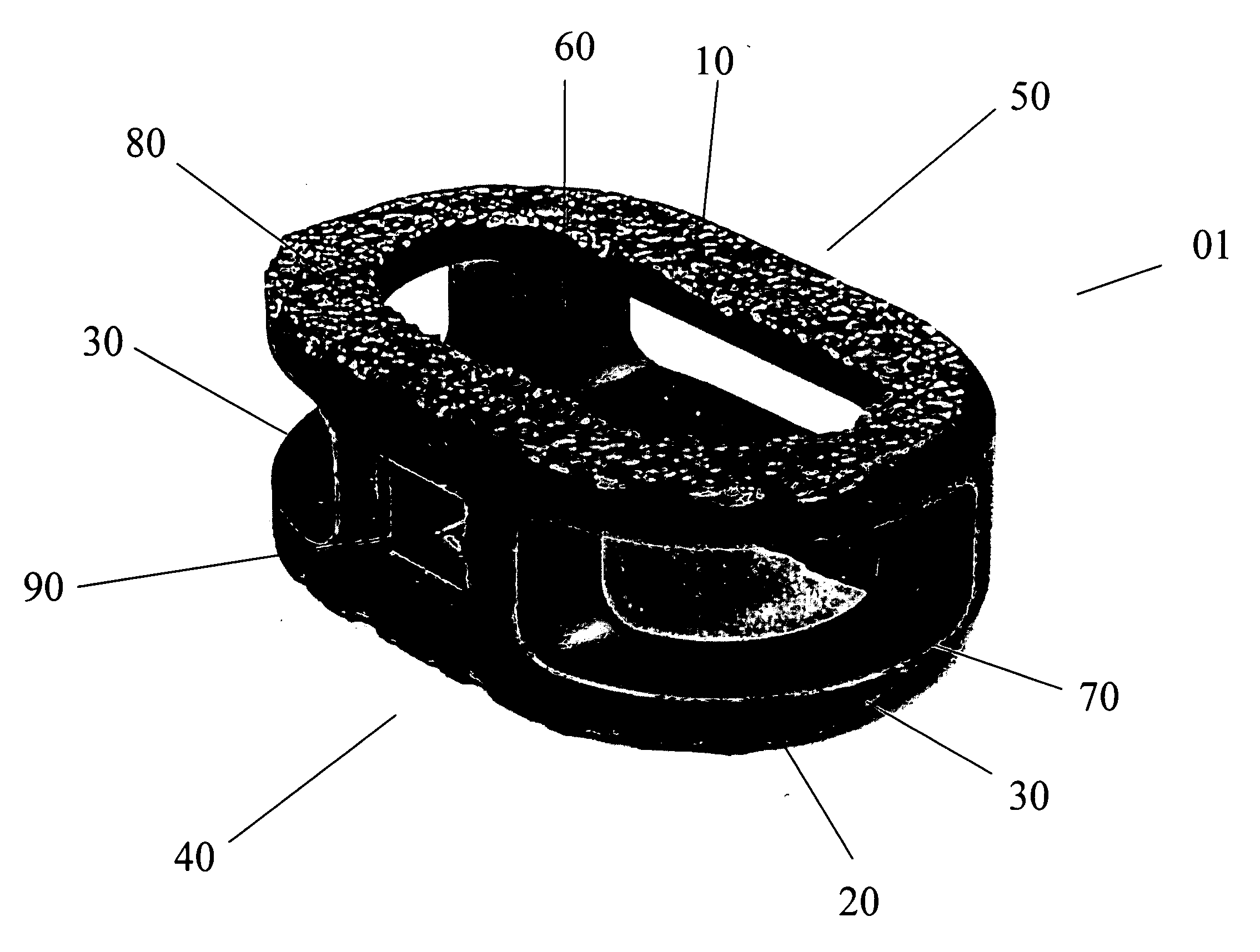
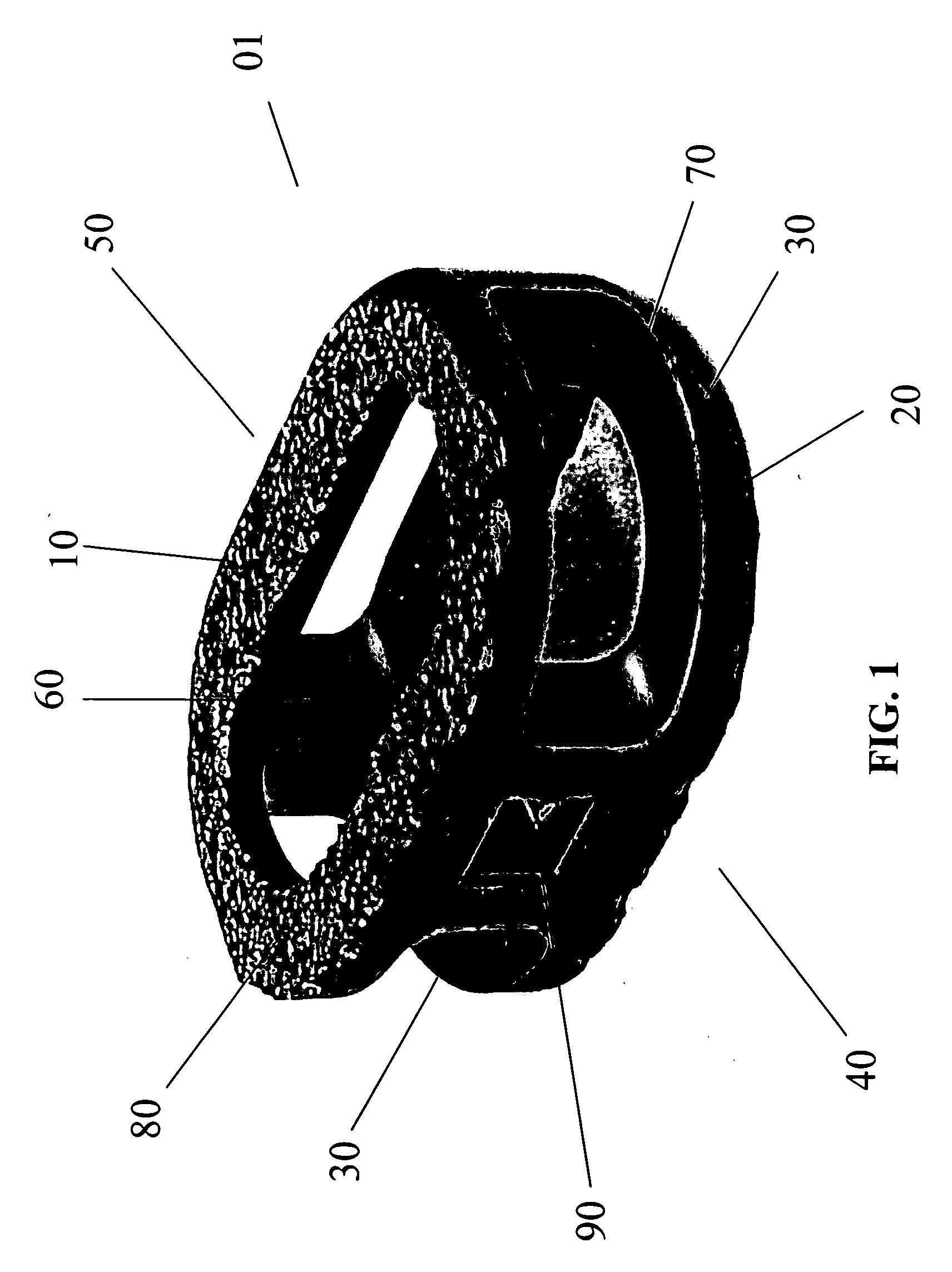
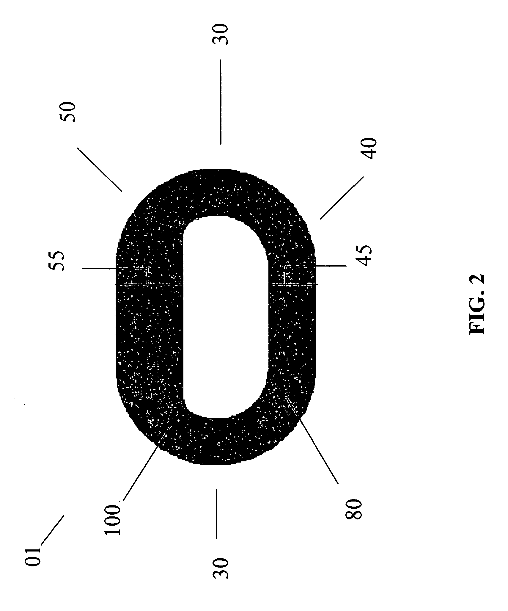
[0031] Certain embodiments of the present invention are particularly suited for use during interbody spinal implant procedures currently known in the art. For example, the disc space may be accessed using a standard mini open retroperitoneal laparotomy approach. The center of the disc space is located by anterior-posterior (AP) fluoroscopy taking care to make sure the pedicles are equidistant from the spinous process. The disc space is then incised by making a window in the annulus for insertion of certain embodiments of the present spinal implant. The endplates are cleaned of all cartilage with a curette and a size-specific rasp may then be used.

[0032] A lateral c-arm fluoroscopy can be used to follow insertion of the rasp in the posterior disc space. The smallest height rasp that touches both endplates (e.g., the superior and inferior endplates) in first chosen. After the disc space is cleared of all soft tissue and cartilage, distraction is then accomplished by using implant tri...


PUM


Abstract

This present invention relates to interbody spinal implants and methods of using such implants. Certain embodiments of the present invention are particularly suitable for placement using an anterior surgical approach. Certain embodiments of the present invention include a body having a top surface, a bottom surface, opposing lateral sides, and opposing anterior and posterior portions. Interbody spinal implants, as now taught, further include roughened surface topography on at least a portion of its top surface and/or bottom surface. Preferred embodiments of the interbody spinal implant are substantially hollow and have a generally oval-shaped transverse cross-sectional area. Preferred embodiments of further include at least one aperture that extends the entire height of the implant body. This vertical aperture also defines a transverse rim having greater posterior thickness than anterior thickness. Certain embodiments also preferably include at least one aperture that extends the entire transverse length of the implant body.

Description

FIELD OF THE INVENTION [0001] This invention relates to interbody spinal implants and methods of using such implants. The spinal implants are further particularly suitable for placement using an anterior surgical approach. BACKGROUND OF THE INVENTION [0002] In the simplest terms, the spine is a column made of vertebrae and discs. The vertebrae provide the support and structure of the spine while the spinal discs, located between the vertebrae, act as cushions or “shock absorbers.” These discs also contribute to the flexibility and motion of the spinal column. Over time, the discs may become diseased, infected, develop deformities such as tears / cracks, or simply lose structural integrity, for example bulge or flatten. These impaired discs can affect the anatomical functions of the vertebrae, due to the resultant lack of proper biomechanical support, and are often associated with chronic back pain. [0003] Several surgical techniques have been developed to address spinal defects, such ...

Claims


Application Information

Patent Timeline
IPC IPC(8): A61F2/44
CPCA61F2/30965A61F2/4465A61F2002/2817A61F2002/2835A61F2002/30785A61F2310/00023A61F2002/30906A61F2002/30925A61F2002/4475A61F2310/00017A61F2002/30836A61F2002/30593
Inventor BAGGA, CHARANPREET S.ULLRICH, PETER F. JR.DORAN, MICHAEL E.
Owner TITAN SPINE
Why Eureka
Try Eureka