Noise filter mounting structure

a technology for mounting structures and noise filters, applied in emergency protective arrangements for limiting excess voltage/current, feed-through capacitors, printed circuit non-printed electric components, etc., can solve the problem that the above-described noise signal cannot be sufficiently grounded, and achieve excellent noise reduction characteristics, reduce stray capacitance, and increase impedance

Active Publication Date: 2006-12-07
MURATA MFG CO LTD
View PDF14 Cites 19 Cited by
  • Summary
  • Abstract
  • Description
  • Claims
  • Application Information

AI Technical Summary

Benefits of technology

[0032] According to a preferred embodiment, since the impedance increaser increases the impedance of the ground side input terminal, the noise signal transmitted from the ground side output terminal to the ground side output electrode is grounded and is prevented from being transmitted to the ground side input terminal via the ground side input electrode. In addition, the noise signal generated at the hot side output electrode is grounded to the ground side output electrode via the stray capacitance between the hot side output electrode and the ground side output electrode. As a result, a mounting structure for a noise filter that can provide excellent noise-reducing characteristics can be obtained.
[0033] According to the first preferred embodiment of the present invention, the impedance increaser includes the structure that reduces the stray capacitance between the ground side input electrode and the ground side output electrode by increasing the gap between the ground side input electrode and the ground side output electrode and that positively utilizes the stray capacitance between the hot side output electrode and the ground side output electrode by reducing the gap between the hot side output electrode and the ground side output electrode. Therefore, the impedance increaser can be obtained without using an additional component, more specifically, simply by changing the patterns of the ground side input electrode, the ground side output electrode, and the hot side output electrode on the circuit board.
[0034] According to a second preferred embodiment of the present invention, the impedance increaser includes the inductor connected between the ground side input electrode and the ground side output electrode. Thus, the impedance can be reliably increased simply by adding, for example, a component like a chip inductor.
[0035] In addition, when the ferrite bead is provided in association with at least the ground side input terminal, the inductance at this portion can be increased, and accordingly the noise reduction effect can be increased.
[0036] In addition, when the feedthrough capacitor is provided in association with at least the hot side output terminal, the noise reduction effect can be increased.

Problems solved by technology

In such cases, the above-described noise signal cannot be sufficiently grounded.

Method used


Image

  • Noise filter mounting structure
  • Noise filter mounting structure
  • Noise filter mounting structure

Examples


Embodiment Construction

[0045] FIGS. 1 to 4 are diagrams for explaining a mounting structure for a noise filter according to a first preferred embodiment of the present invention.

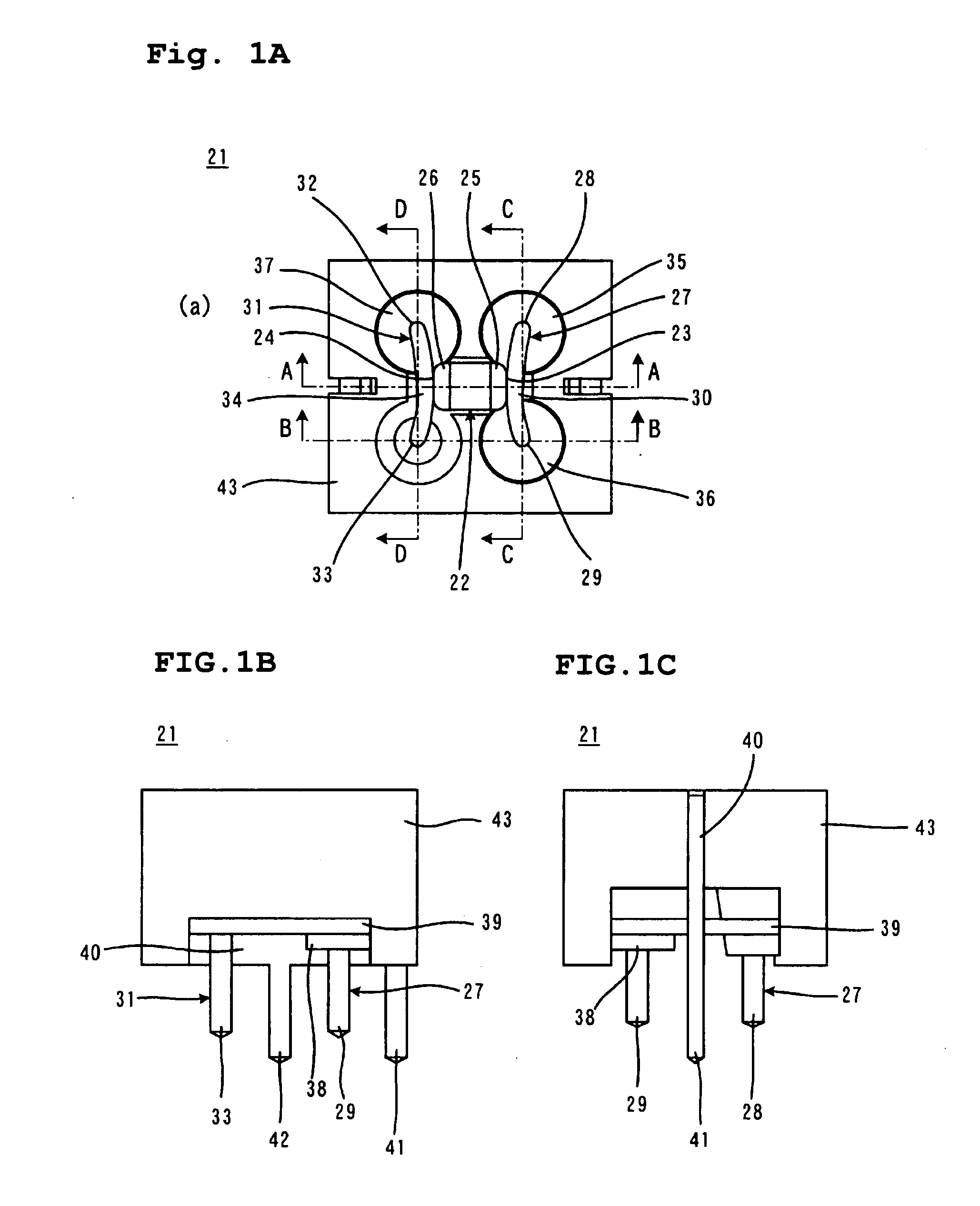
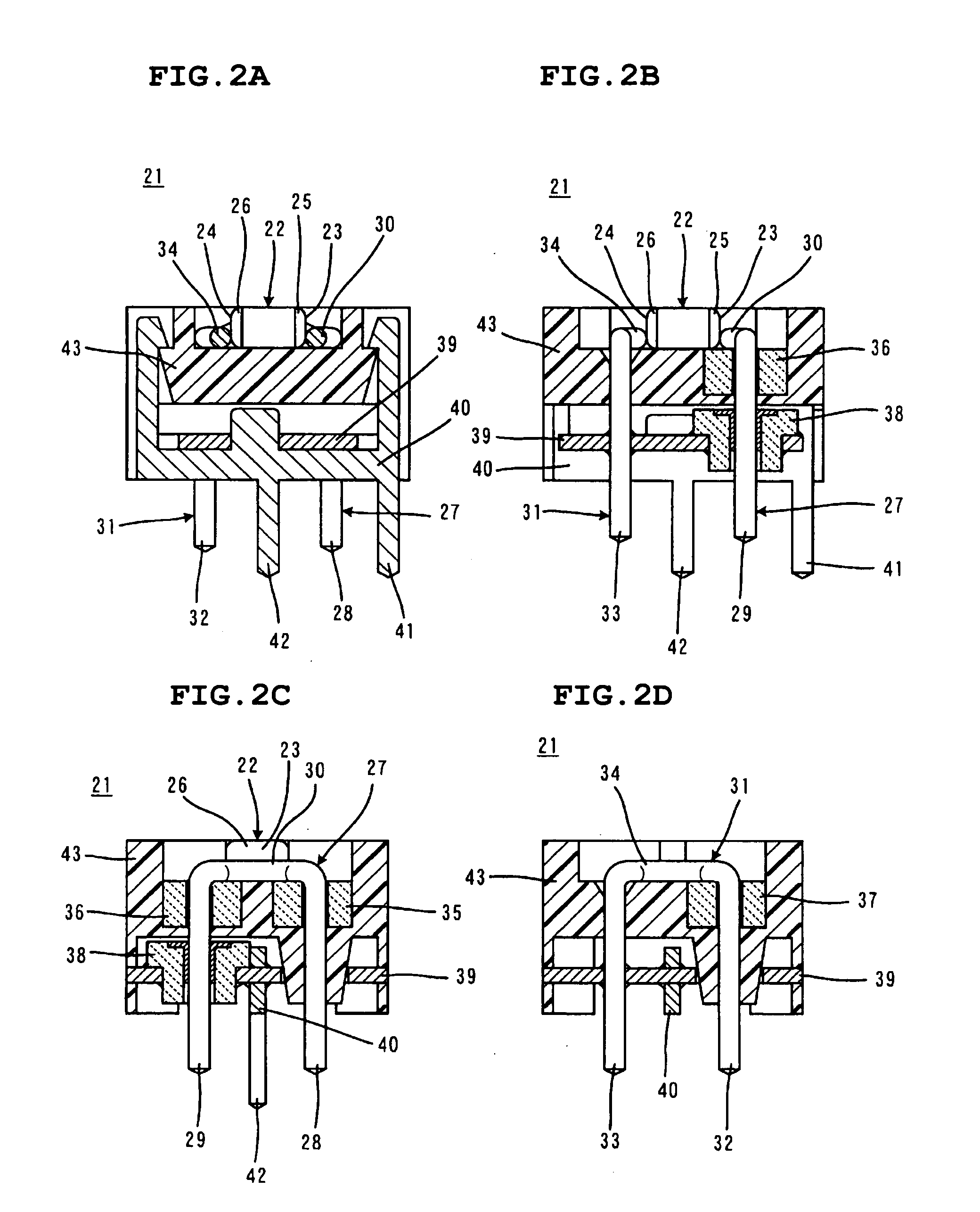
[0046] FIGS. 1(A)-(D) illustrate an external view of a-noise filter 21, where FIGS. 1(A), 1(B), and 1(C) are a top view, a front view, and a right side view, respectively. FIGS. 2(A)-(D) illustrate sectional views of the internal structure of the noise filter 21, where 2(A), 2(B), 2(C), and 2(D) are sectional views taken along lines A-A, B-B, C-C, and D-D, respectively, in FIG. 1(A).

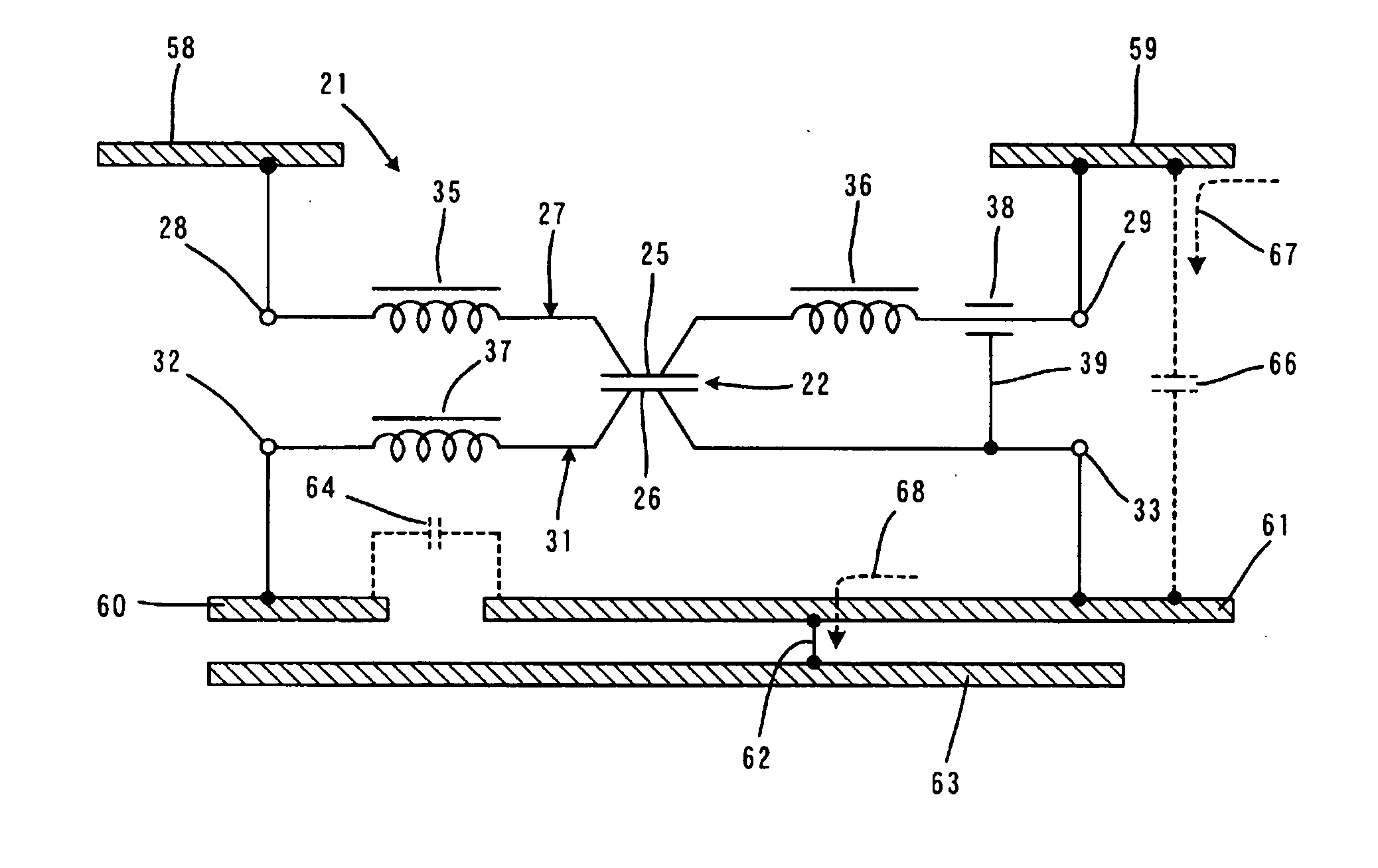
[0047] The noise filter 21 shown in the figures is an LC composite component that functions as an EMI suppression filter.

[0048] The noise filter 21 includes a capacitor 22 having a chip-like shape that functions as a four-terminal capacitor. The capacitor 22 includes, for example, a monolithic ceramic capacitor. The capacitor 22 is provided with first and second terminal electrodes 25 and 26 on first and second end surfaces 23 and 24, respectively, ...


PUM

PropertyMeasurementUnit
impedanceaaaaaaaaaa
stray capacitanceaaaaaaaaaa
shapeaaaaaaaaaa

Abstract

A noise filter includes a capacitor having a hot side input terminal, a hot side output terminal, a ground side input terminal, and a ground side output terminal. A circuit board includes a hot side input electrode connected to the hot side input terminal, a hot side output electrode connected to the hot side output terminal, a ground side input electrode connected to the ground side input terminal, and a ground side output electrode connected to the ground side output terminal. The impedance of the ground side input terminal seen from the ground side output electrode is larger than both the impedance of the ground side output terminal seen from the ground side output electrode and the impedance of the hot side output terminal seen from the ground side output electrode. For this purpose, a stray capacitance formed between the ground side input electrode and the ground side output electrode is reduced by increasing a gap therebetween. Accordingly, excellent noise-reducing characteristics are provided.

Description

BACKGROUND OF THE INVENTION [0001] 1. Field of the Invention [0002] The present invention relates to mounting structures for noise filters, and more particularly, to a mounting structure for a noise filter including a four-terminal capacitor. [0003] 2. Description of the Related Art [0004] FIGS. 6(A) and 6(B) illustrate a known noise filter relevant to the present invention (see, for example, Japanese Examined Utility Model Registration Application Publication No. 1-22258, Japanese Examined Utility Model Registration Application Publication No. 2-18587, and Japanese Examined Utility Model Registration Application Publication No. 6-31777). FIGS. 6(A) and 6(B) are a top view and a right side view, respectively, of a noise filter 1. [0005] With reference to FIGS. 6(A) and 6(B), the noise filter 1 includes a four-terminal capacitor 2. The capacitor 2 has a chip-like shape and is provided with first and second terminal electrodes 5 and 6 on first and second end surfaces 3 and 4, respecti...

Claims


Application Information

Patent Timeline
Patent Type & Authority Applications(United States)
IPC IPC(8): H02H9/06H01F17/06H01F27/40H01G4/35H01G4/40H03H1/00H05K1/02H05K1/18
CPCH01F17/06H01F27/40H01F2017/065H01G4/35H05K2201/10969H03H1/0007H05K1/0243H05K1/18H05K2201/1006H01G4/40H03H7/075
Inventor SAITO, KENICHIOSHIMA, HISATOOOI, TAKAAKIMURAKAMI, TOSHINORITANAKA, YOSHIMI
Owner MURATA MFG CO LTD
Why Eureka
Try Eureka