Differential Gearing for Vehicle

a differential gearing and vehicle technology, applied in the direction of gearing details, belts/chains/gearrings, gearing details, etc., can solve the problem of cumbersome assembly and achieve the effect of facilitating assembly

a differential gearing and vehicle technology, applied in the direction of gearing details, belts/chains/gearrings, gearing details, etc., can solve the problem of cumbersome assembly and achieve the effect of facilitating assembly

US20060287155A1Inactive Publication Date: 2006-12-21JTEKT CORP

Image

  • Differential Gearing for Vehicle
  • Differential Gearing for Vehicle
  • Differential Gearing for Vehicle

Examples


Embodiment Construction

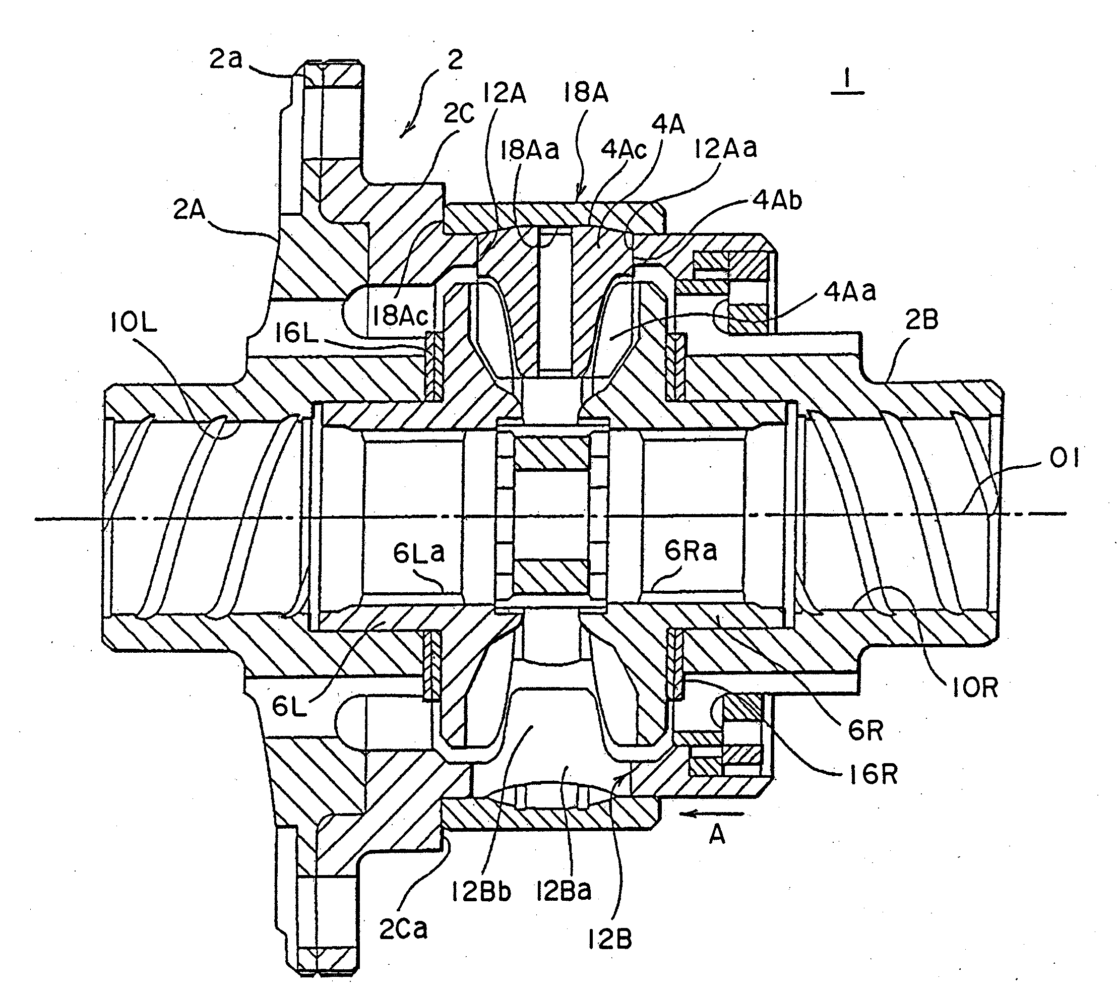
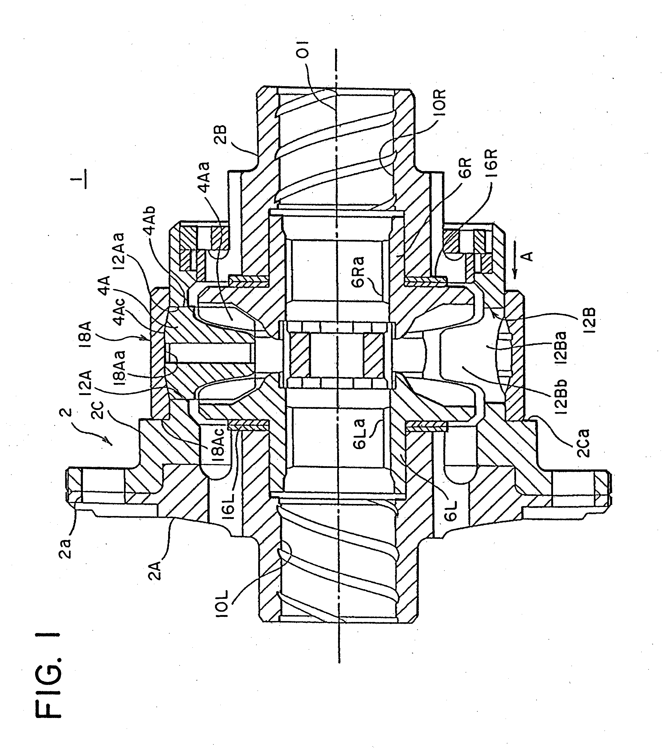
[0022] Several embodiments of the invention shown in the drawings will now be described. A differential gearing for vehicle 1 according to this embodiment includes a differential case 2, which is of a three-piece construction. A disk-shaped, first case 2A disposed to the left as viewed in FIG. 1, a cylindrical, second case 2B of a smaller diameter which is located to the right and a substantially cylindrical, third case 2C disposed therebetween are disposed in abutment against each other and are secured together as by bolts.

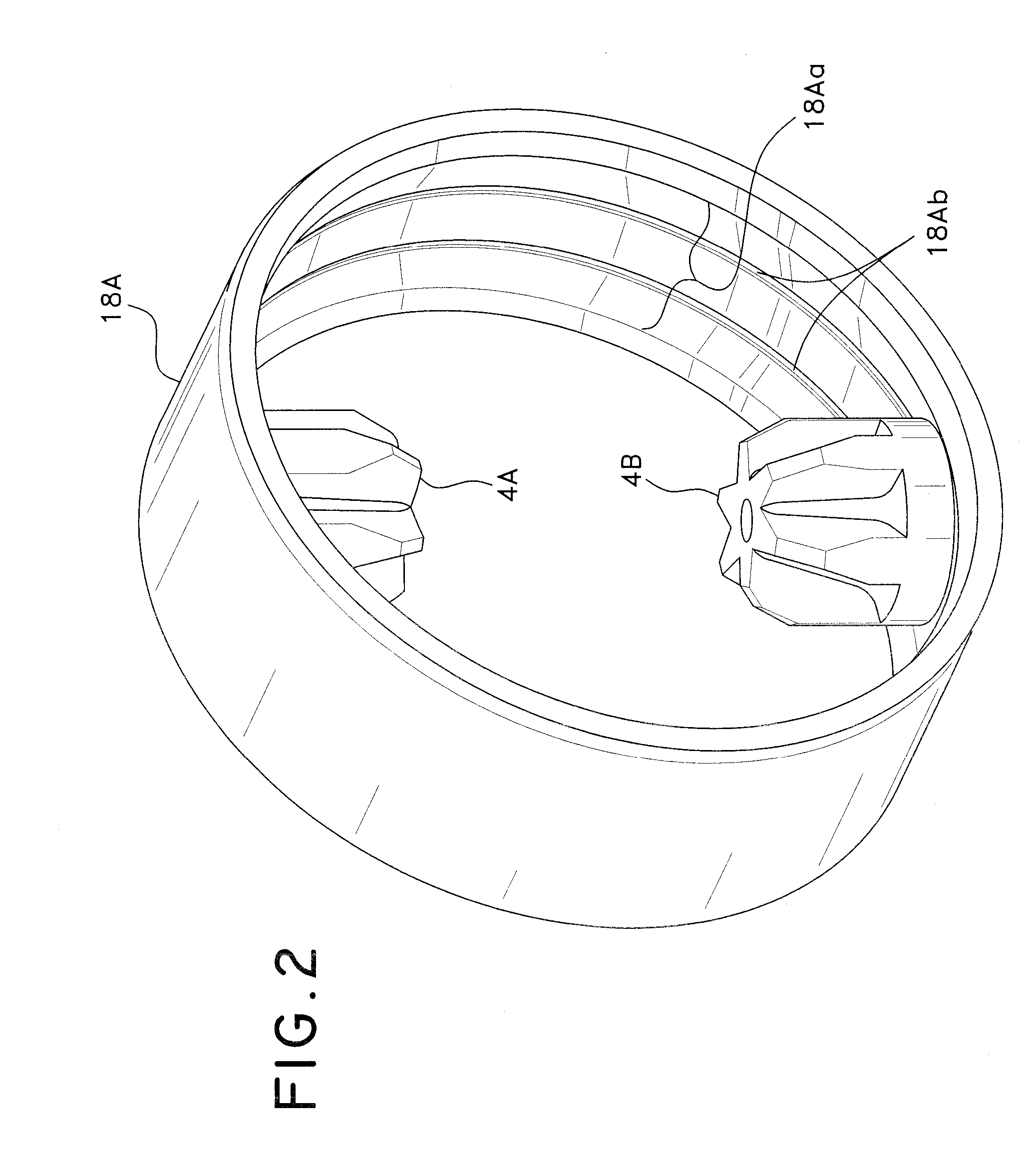
[0023] The differential gearing for vehicle 1 comprises two pinion gears 4A (one being not shown) which are rotatably held within the differential case 2, and a pair of left and right side gears 6L, 6R received within the differential case 2 and disposed to be in meshing engagement with both pinion gears 4A simultaneously and connected to left and right axles (not shown) by splines 6La, 6Ra which are formed in their inner peripheral surfaces.

[0024] The differen...


PUM


Abstract

A plurality of pinion gears 4A, 4B which are rotatably held within a differential case 2, and a pair of left and right side gears 6L, 6R which are in meshing engagement with the pinion gears 4A, 4B and connected to left and right axles are provided. A ring 18A is fitted around the pinion gears 4A, 4B to prevent the pinion gears 4A, 4B from being withdrawn. The ring 18A has an inner peripheral surface in which a spherical recess 18Aa centered about a point of intersection between an axis of rotation of the side gears 6L, 6R and an axis of rotation of the pinion gears 4A, 4B is formed while an end of the pinion gears 4A, 4B which is disposed toward the outer periphery is formed with a spherical projection 4Ac having a similar curvature as the recess in the ring 18A.

Description

CROSS-REFERENCE TO RELATED APPLICATIONS [0001] This application is based upon and claims priority under 35 USC §119 to Japanese Patent Application No. 2005-178579 filed on Jun. 17, 2005, the entire contents of which are incorporated herein by reference. BACKGROUND OF THE INVENTION AND RELATED ART STATEMENT [0002] The present invention relates to a differential gearing for vehicle comprising a plurality of pinion gears which are rotatably held within a differential case and a pair of side gears disposed in meshing engagement with the pinion gears and connected to left and right axles, respectively, and in particular, to a differential gearing for vehicle in which a removal of the pinion gears is prevented by a ring which is fitted around the differential case. [0003] A conventional differential gearing for vehicle is known as having a construction as disclosed in Japanese Utility Model No. 2520728, for example. This differential gearing for vehicle of the prior art will be briefly de...

Claims


Application Information

Patent Timeline
21 Dec 2006
Publication
US20060287155A1
IPC
F16H48/06; F16H48/08; F16H48/38; F16H48/40; F16H57/023; F16H57/037; F16H57/038; F16H57/039
CPC
F16H48/08; F16H2048/082; F16H2048/387; F16H2048/087; F16H2048/382; F16H2048/085
Inventors
NAKAJIMA, SHINICHIRO