

Heat exchanger
- Summary
- Abstract
- Description
- Claims
- Application Information
AI Technical Summary
Benefits of technology
Problems solved by technology
Method used
Image

Examples
Embodiment Construction
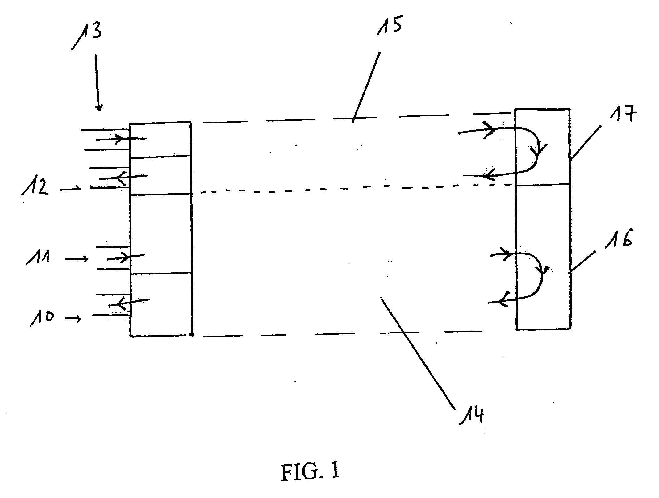
[0024] Referring to FIG. 1, manifold inlet (13) and outlet (12) for oil cooler element (15) is shown, with oil cooler section of manifold (17) described. Condenser section of manifold (16) is also shown with oil cooler element (15) above condenser element (14).
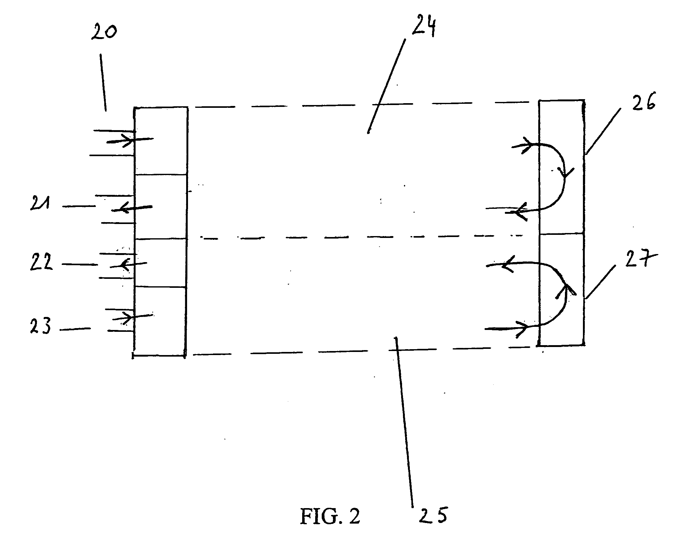
[0025] Referring to FIG. 2, manifold inlet (23) and outlet (24) for oil cooler element (25) is shown, with oil cooler section of manifold (27) described. Condenser section of manifold (26) is also shown with oil cooler element (25) below condenser element (24).
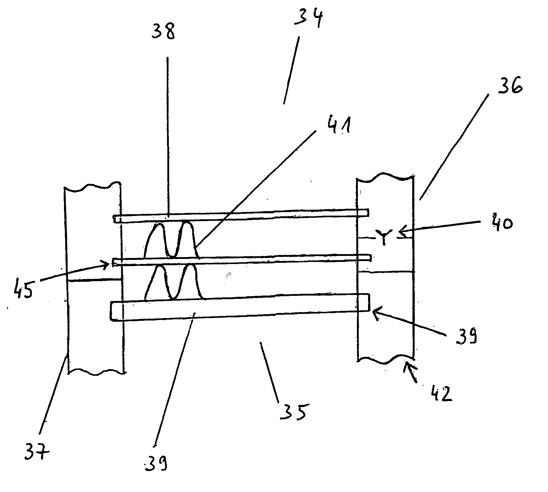
[0026] Referring to FIG. 3, a combo-cooler (34), a controlling device (40) controlling mass flow rate through the last condenser tube (45) prior to leaving the condenser portion is shown.
[0027]FIG. 3 shows a condenser element (38) and transmission oil cooler element last tube (39). Manifold (37) and manifold tube portions (36,42) are illustrated as well as fins (41).
[0028] Referring to FIG. 4, is shown a thermal duty map graphic representation of performance of a spo...
PUM
 Abstract
Description
Claims
Application Information