Reformer for fuel cell

a fuel cell and reformer technology, applied in electrochemical generators, chemical/physical/physicochemical processes, bulk chemical production, etc., can solve the problems of dmfc depreciation in its practical value, the problem of miniaturization of fuel cells, and the improvement of functions and services, so as to prevent heat loss, improve heat absorption, and improve the effect of heat absorption

Inactive Publication Date: 2007-03-29
SAMSUNG ELECTRO MECHANICS CO LTD
View PDF7 Cites 0 Cited by
  • Summary
  • Abstract
  • Description
  • Claims
  • Application Information

AI Technical Summary

Benefits of technology

[0035] The present invention has been made to solve the foregoing problems of the prior art and therefore an object of certain embodiments of the present invention is to provide a reformer for a fuel cell system with superior heat characteristics having a porous part in a part of the base corresponding to an evaporating part to increase heat absorption, preventing losses of heat, thereby increasing heat efficiency of the evaporating part while supplying sufficient heat to the evaporating part with minimal energy.

Problems solved by technology

However, as there are many problems with the storage of oxygen in practice, air containing much oxygen is used, and the reactions occurring in the fuel cell are as follows.
For the portable apparatuses such as the notebook computers or mobile phones, the major issues have been improvement of functions and services, and in particular, miniaturization.
Thus, the main issue for the fuel cells has been miniaturization as well.
However, with significantly low output density, the DMFC is depreciated in its practical value although it is much researched for supplying power to the portable apparatuses.
In addition, although the overall size is reduced, many problems are incurred in the processes such as forming the flow paths in the multiple layers of cells.
However, it is difficult to use the above described reformer for practical purposes with varying temperatures according to the heights of different parts of the reformer, difficulty of insulating the high temperature, and the insignificant amount of hydrogen output.
This reformer however has only the heating wires provided in the cell or on the substrate without including means to effectively deter the heat from being transferred to the outside.
If the losses of heat occur, not only the heat characteristics of the reformer are degraded but also more thermal energy is required to evaporate the fuel, thus resulting in other operational problems of the reformer.
Such degradation of the heat characteristics negatively affects the two major operational characteristics of the reformer, i.e., evaporating and reforming functions.

Method used


Image

  • Reformer for fuel cell
  • Reformer for fuel cell
  • Reformer for fuel cell

Examples


Embodiment Construction

[0058] Preferred embodiments of the present invention will now be described in detail with reference to the accompanying drawings.

[0059] The reformer 1 (in particular, micro reformer) for a fuel cell according to certain embodiments of the present invention is aimed to mitigate the difficulty of maintaining the heat characteristics of the conventional reformer and increase a catalyst area to increase catalytic capability. Thus, ultimately, the reformer 1 of the invention is aimed to generate high-purity hydrogen gas with removal of CO, thereby enhancing the output density of the fuel cell supplied with the hydrogen gas.

[0060] The reformer for a fuel cell according to the present invention is one used in the PEMFC which mainly uses hydrogen (gas) as fuel.

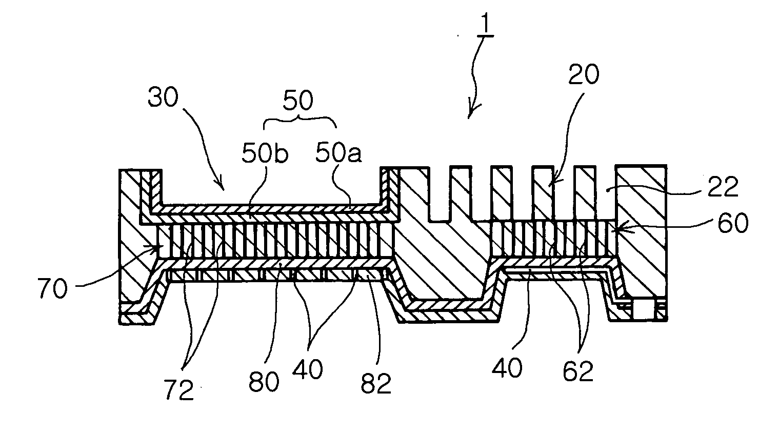
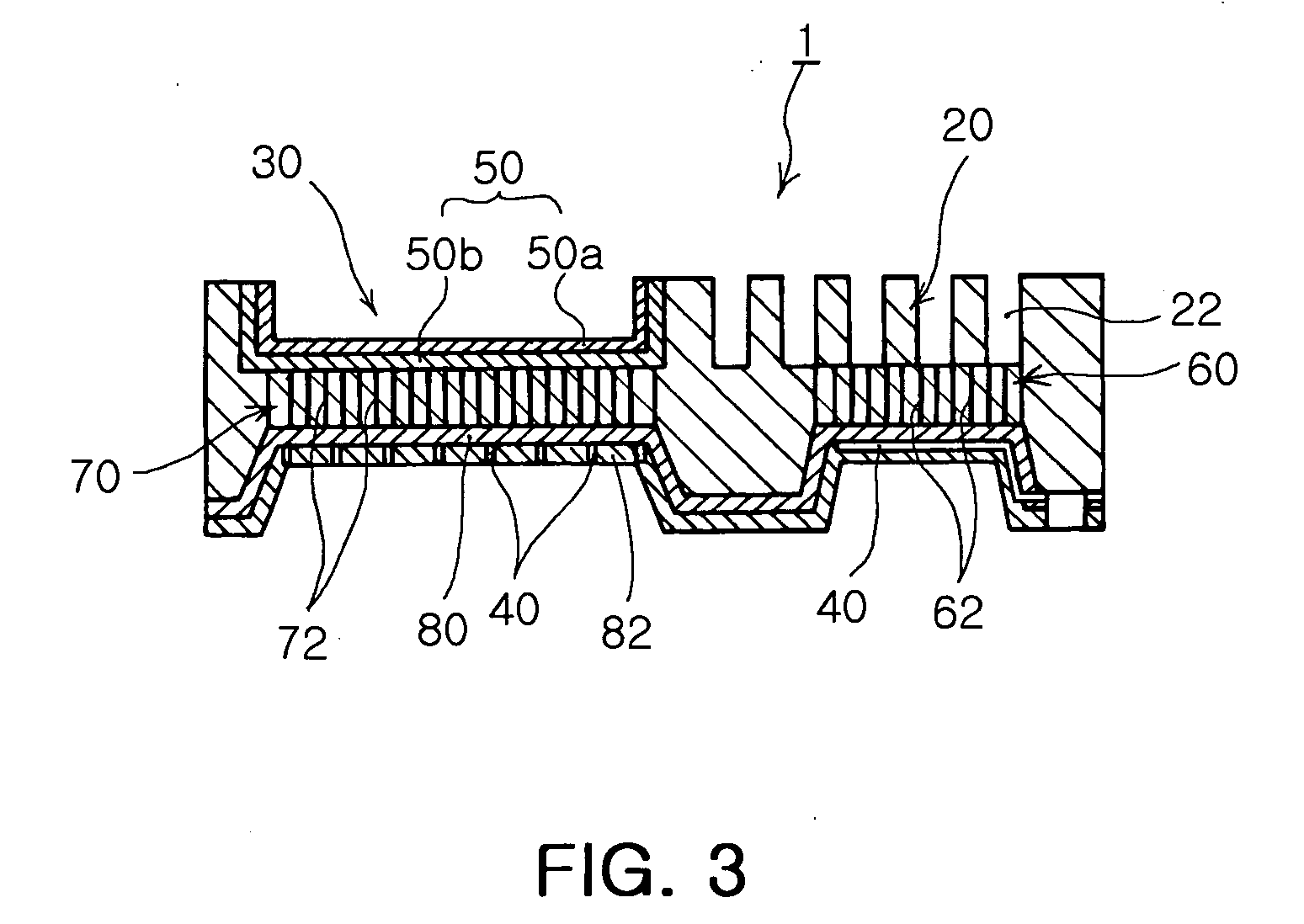
[0061]FIGS. 3 and 4 illustrate the reformer 1 for a fuel cell with superior heat characteristics according to the present invention.

[0062] As shown in FIGS. 3 and 4, the reformer 1 according to the present invention includes a ba...


PUM


Abstract

The invention relates to a reformer with superior heat characteristics for supplying hydrogen gas as fuel to a fuel cell of a fuel cell system. The reformer includes a base having an evaporating part, a reforming part and flow paths each formed in the evaporating part and the reforming part. The reformer also includes heaters each attached on the base corresponding to the positions of the evaporating part and the reforming section. The reformer further includes a catalyst disposed in the reforming section of the base and a porous part integrally formed in a portion of the base extending from the evaporating part to the heater. The reformer has the porous part including nano-pores to increase heat absorption, preventing heat losses. This allows increased heat efficiency and sufficient heat supply with minimal energy, thereby enhancing operational characteristics of the reformer.

Description

CLAIM OF PRIORITY [0001] This application claims the benefit of Korean Patent Application No. 2005-91385 filed on Sep. 29, 2005, in the Korean Intellectual Property Office, the disclosure of which is incorporated herein by reference. BACKGROUND OF THE INVENTION [0002] 1. Field of the Invention [0003] The present invention relates to a reformer for supplying hydrogen gas as a fuel to a fuel cell of a fuel cell system. More particularly, the invention relates to a reformer with superior heat characteristics, which has a porous part with nano-pores formed in a portion of a base corresponding to an evaporating part to prevent heat losses with increased heat absorption capacity of the porous part, thereby increasing heat efficiency of the evaporating part and allowing sufficient heat supply with a small amount of energy. [0004] 2. Description of the Related Art [0005] In recent years, as energy depletion and environmental pollution have become important issues, attention and development ...

Claims


Application Information

Patent Timeline
Patent Type & Authority Applications(United States)
IPC IPC(8): B01J19/00
CPCB01J19/0093H01M8/0668B01J2219/00783B01J2219/00788B01J2219/00822B01J2219/00828B01J2219/00831B01J2219/00835B01J2219/00844B01J2219/00873B01J2219/00891B01J2219/2453B01J2219/2458B01J2219/2479B01J2219/2485B01J2219/2486B01J2219/2488B01J2219/2495C01B3/384C01B2203/0227C01B2203/066C01B2203/085C01B2203/1076C01B2203/1288H01M8/0612B01J19/249Y02E60/50Y02P20/52B82Y40/00C01B3/26C01B3/38
Inventor LEE, RO WOONKIM, SANG JIN
Owner SAMSUNG ELECTRO MECHANICS CO LTD
Why Eureka
Try Eureka