Electrical Machine Comprising Cooling Channels

a technology of cooling channels and electric machines, applied in the field of electric machines, can solve problems such as non-uniform temperature distribution over the axial length of electrical machines

Active Publication Date: 2014-03-13
ROBERT BOSCH GMBH
View PDF8 Cites 14 Cited by
  • Summary
  • Abstract
  • Description
  • Claims
  • Application Information

AI Technical Summary

Benefits of technology

[0005]An electrical machine, in particular for a motor vehicle, comprising a housing, a shaft having an axis, a stator and a rotor, at least one channel for conducting a cooling fluid for cooling the electrical machine, with the geometry or the orienta

Problems solved by technology

This leads to non-uniform temperature distributio

Method used


Image

  • Electrical Machine Comprising Cooling Channels
  • Electrical Machine Comprising Cooling Channels
  • Electrical Machine Comprising Cooling Channels

Examples


Embodiment Construction

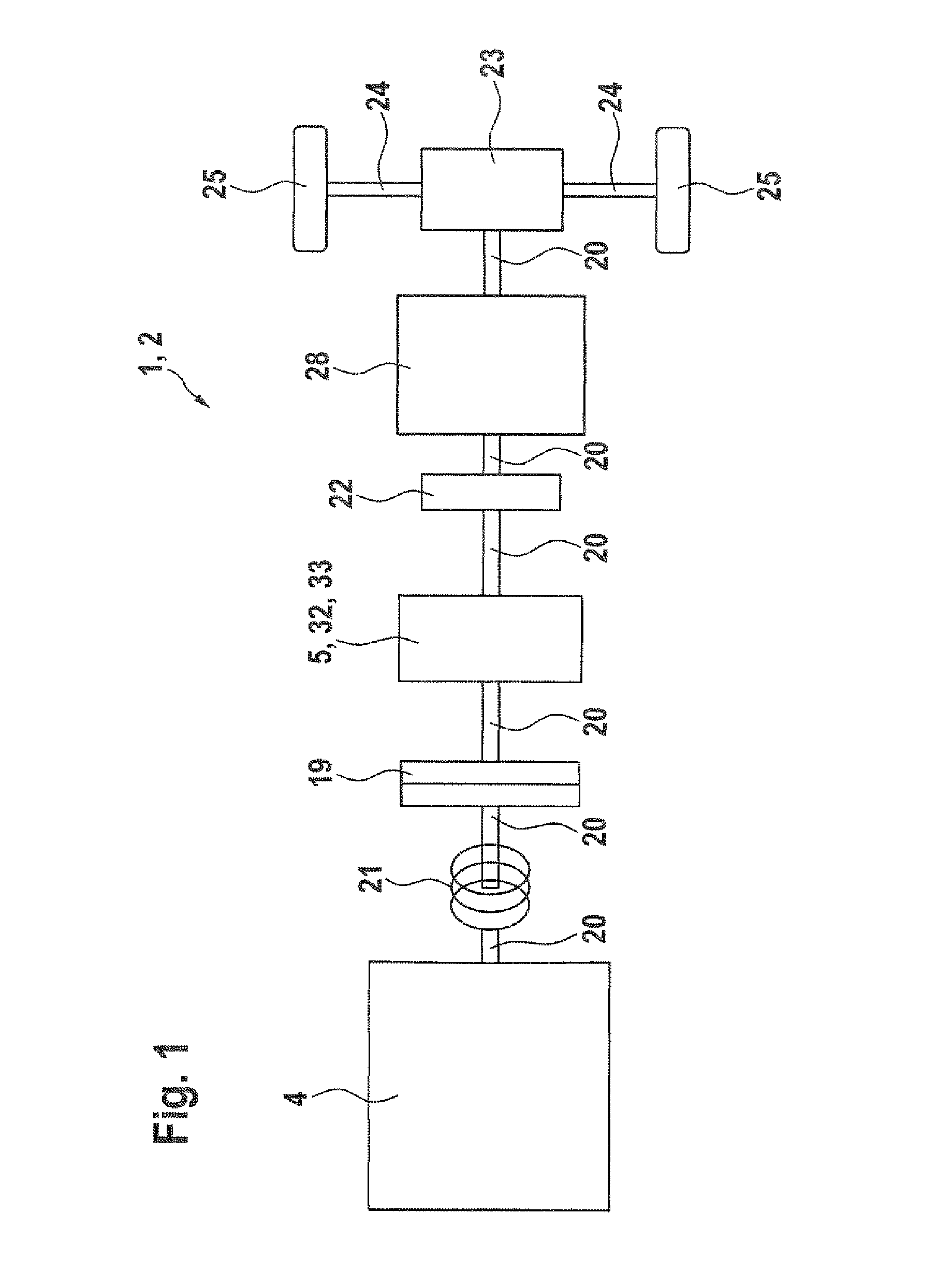
[0034]A drive device 1, in the form of a hybrid drive device 2, for a motor vehicle 3 is illustrated in FIG. 1. The hybrid drive device 2 for a motor vehicle 3 comprises an internal combustion engine 4 and also an electrical machine 5 which operates as a motor 32 and a generator 33, in each case for driving or decelerating the motor vehicle 3. The internal combustion engine 4 and the electrical machine 5 are connected to one another by means of a drive shaft 20. The mechanical coupling between the internal combustion engine 4 and the electrical machine 5 can be established and broken by means of a clutch 19. Furthermore, an elasticity means 21 is arranged in the drive shaft 20 which couples the internal combustion engine 4 and the electrical machine 5 to one another. The electrical machine 5 is mechanically coupled to a differential transmission 23. A converter 22 and a transmission 28 are arranged in the drive shaft 20 which connects the electrical machine 5 and the differential tr...


PUM


Abstract

The invention relates to an electric motor, in particular for a motor vehicle, comprising a housing (9), a shaft (8) having an axle (30), a stator and a rotor, at least one channel (11) for conducting a coolant for cooling the electric motor (5), wherein the geometry of the alignment of at least one section (12) of the at least one channel (11) is designed such that the coolant flows in the direction of the axle (30) of the shaft (8) through the at least one channel (11), having a deviation of less than 40°.

Description

BACKGROUND OF THE INVENTION[0001]The present invention relates to an electrical machine and to a drive device.[0002]Drive devices, preferably hybrid drive devices, in particular comprising an internal combustion engine and an electrical machine, are used, for example, in order to drive motor vehicles. The electrical machine in the motor vehicle, which electrical machine operates as a motor and a generator, has an axle or shaft on which the stator or rotor is arranged.[0003]Waste heat is produced in the electrical machine, in particular in the stator and / or rotor, and therefore it is necessary to cool the electrical machine. The stator and rotor are arranged within a housing of the electrical machine. A spiral or helical channel for conducting a cooling fluid for cooling the electrical machine is incorporated in the housing. The axle around which the spiral cooling channel is wound corresponds to the axis of the shaft of the electrical machine in this case. After the cooling fluid is...

Claims


Application Information

Patent Timeline
IPC IPC(8): H02K9/00H02K9/19B60L50/16
CPCH02K9/005Y10S903/902H02K9/19B60L3/0061B60L2210/40B60L2240/36B60L2240/425B60L50/16Y02T10/64Y02T10/72Y02T10/7072H02K5/203Y02T10/70H02K9/00
Inventor ROHWER, THORSTENKERN, DENISHERZBERGER, ANDREAS
Owner ROBERT BOSCH GMBH
Why Eureka
Try Eureka