Driving device

a driving device and drive system technology, applied in the direction of engine cooling apparatus, non-fuel substance addition to fuel, lighting and heating apparatus, etc., can solve the problems of system becoming very voluminous, increasing the temperature of the drive system, and requiring a portion of the engine's energy for ventilation, so as to achieve a small design and increase the cooling power

Inactive Publication Date: 2010-08-26
AMOVIS
View PDF15 Cites 16 Cited by
  • Summary
  • Abstract
  • Description
  • Claims
  • Application Information

AI Technical Summary

Benefits of technology

[0009]It is an object of the invention to provide a drive system of the above mentioned kind with a cooling device which has an increased cooling power and which can have a smaller design.

Problems solved by technology

However, this causes the problem that the ventilation itself requires a portion of the energy of the engine.
The covering of the energy consumption may cause a further increase of the temperature of the drive system.
Two containers are used in such a system and a large amount of water steam is generated thereby causing the system to become very voluminous.
Thereby, the cooling system is even more stressed.

Method used


Image

  • Driving device
  • Driving device

Examples


Embodiment Construction

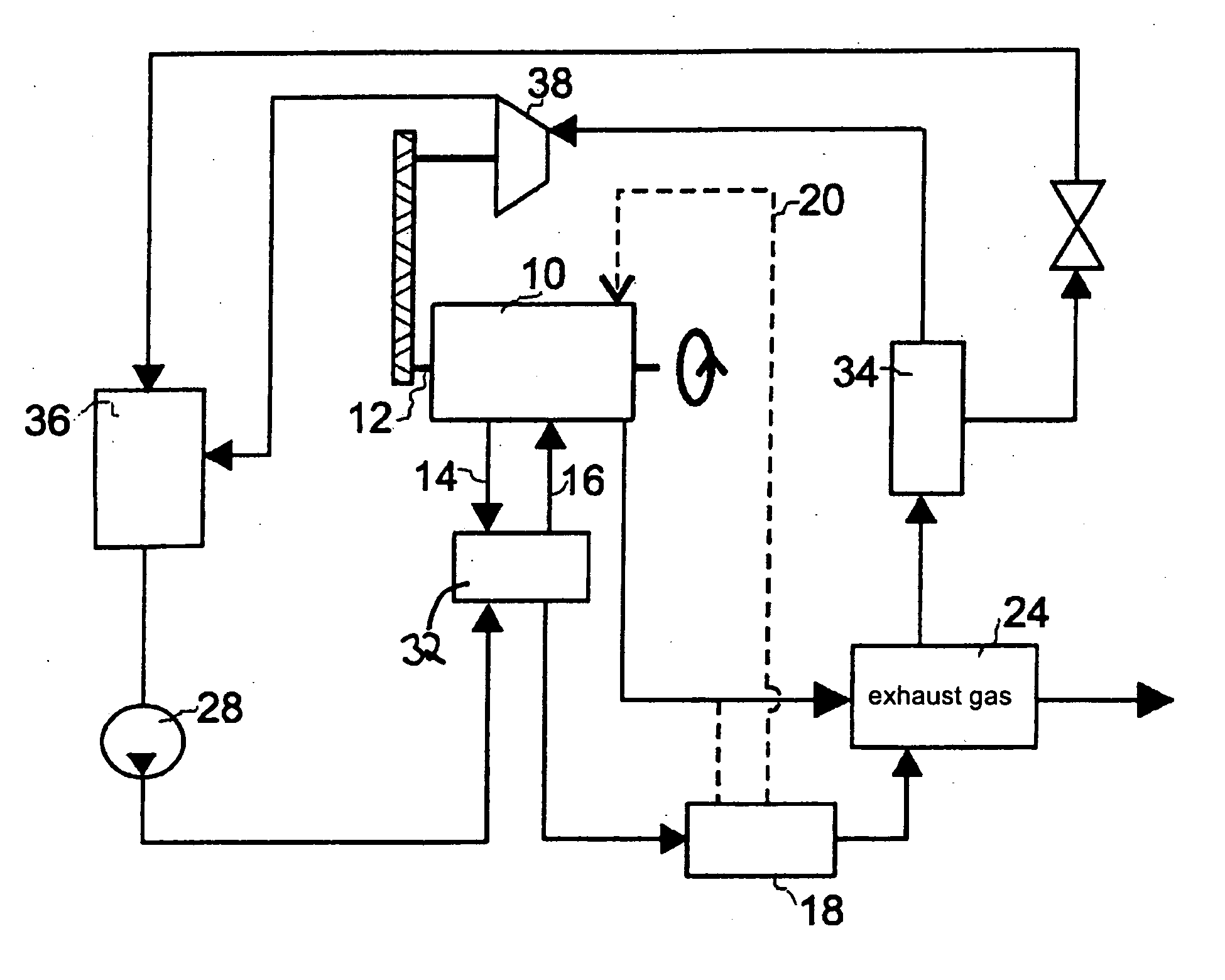
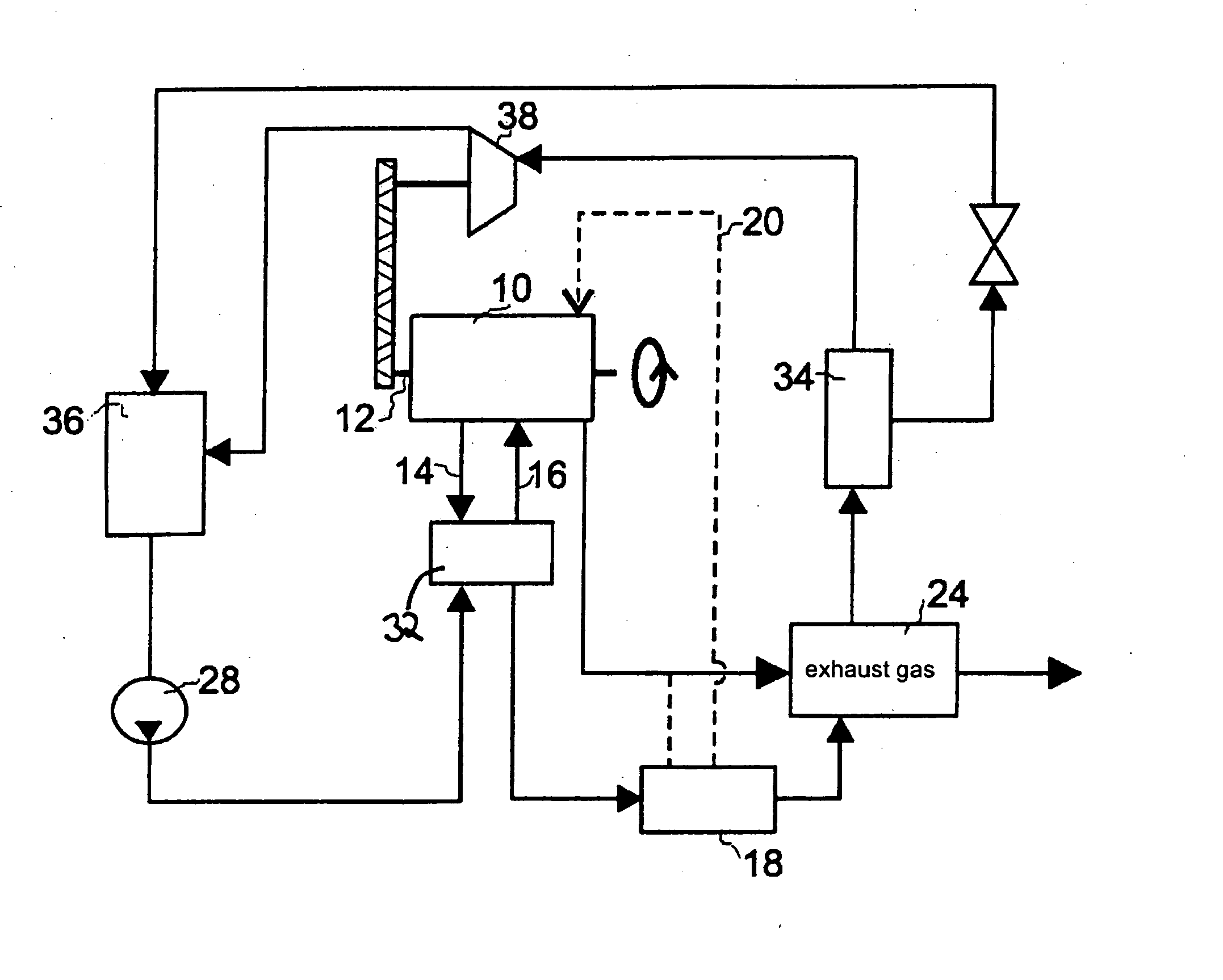
[0026]In the FIGURE an embodiment of the invention is schematically shown using the example of a charged diesel engine for cars. It is understood that the invention is also suitable for any other combustion engine and that apart from cars also trucks, trains, farm machines and the like can be driven.

[0027]The diesel engine is generally denoted with numeral 10. The diesel engine 10 drives a driving shaft 12. The way of operation of a diesel engine is commonly known prior art and must, therefore, not be described here in greater detail. The diesel engine 10 operates with a power range of typically 100 kW. It produces waste heat in the range of 250 kW. The generated waste heat is transferred to the cooling water of a first cooling system 14 and 16, respectively. On the other hand, hot exhaust gas is generated a portion of which is recycled by recirculation to the engine in an exhaust gas recirculation system 18 to avoid the formation of damaging emissions. This is represented by a dott...


PUM


Abstract

The invention relates to a drive system for motor vehicles comprising a waste heat-producing internal combustion engine and a circuit for draining off at least partially said waste heat with a working fluid which is relievable in an expansion machine, wherein said working fluid comprises several components, wherein at least one component is transferable into a gas phase by absorbing heat of the internal combustion engine and/or another source inside the drive system which also comprises means for separating the liquid fraction from the working fluid prior to the expansion machine pressure removal. The internal combustion engine can be cooled by a first cooling circuit. A second cooling circuit can be used in such a way that the first cooling circuit is cooled thereby.

Description

TECHNICAL FIELD[0001]The invention relates to a drive system for motor vehicles comprising a combustion engine generating waste heat and a circuit for removing at least a portion of this waste heat by means of a working fluid which is adapted to be expanded in an expansion machine.[0002]The invention also relates to a working fluid for the use in such a drive system and its use.[0003]Such a drive system is, for example, an engine with internal combustion, such as a Diesel- or Otto engine in a car or a truck. The combustion engine combusts fuel in a cylinder. The combustion heat generated therein is converted into mechanical energy. This mechanical energy is transferred to a driving shaft which is used to drive the vehicle. The working fluid in known cooling circuits is normally water.[0004]Due to thermodynamic laws it is practically not possible to use the entire heat generated in the system. Therefore, a large amount of waste heat is generated which is disposed off to the environme...

Claims


Application Information

Patent Timeline
Patent Type & Authority Applications(United States)
IPC IPC(8): F01N5/02F02M25/07F01P9/02F28D15/00
CPCF01K23/065F01K25/06F01K25/065Y02T10/166F02G5/02Y02T10/16F01N5/02Y02T10/12
Inventor HOETGER, MICHAEL
Owner AMOVIS
Why Eureka
Try Eureka