Fuel cell vehicle and control method thereof

a fuel cell and vehicle technology, applied in battery/fuel cell control arrangement, electrochemical generators, transportation and packaging, etc., can solve the problems of excessive fuel cell temperature rise, limited performance of cooling devices mounted on vehicles,

Active Publication Date: 2018-08-23
TOYOTA JIDOSHA KK
View PDF18 Cites 11 Cited by
  • Summary
  • Abstract
  • Description
  • Claims
  • Application Information

AI Technical Summary

Benefits of technology

[0006]According to one aspect of the disclosure, there is provided a control method of a fuel cell vehicle equipped with a fuel cell as at least one driving energy source. The fuel cell vehicle comprises a cooling system configured to cool down the fuel cell and a cooling system controller configured to control a cooling power of the cooling system. The cooling system controller has an ordinary control mode as a control mode of controlling the cooling power of the cooling system, wherein the ordinary control mode changes the cooling power of the cooling system to cause a temperature of the fuel cell to be within a predetermined reference temperature range, when it is determined that the temperature of the fuel cell is out of the predetermined reference temperature range, by using at least one of the temperature of the fuel cell, an amount of power generation by the fuel cell and a load request in the fuel cell vehicle. The control method of the fuel cell vehicle comprises estimating a load applied to an own vehicle that is the fuel cell vehicle and that is expected to run on an estimated route, by using at least one of current traffic flow information indicating a current traffic flow on the estimated route, past traffic flow information on the estimated route, a driving history of the own vehicle and a first parameter showing a past driving habit of the own vehicle and indicating a driving tendency of the own vehicle that is different from driving tendencies of other vehicles, in addition to the estimated route where the own vehicle is expected to run; determining whether an overload area that is an area where the temperature of the fuel cell is higher than an appropriate temperature range is present on the estimated route, by using the estimated load; and when determining that the overload area is present on the estimated road, performing an increasing process of increasing the cooling power of the cooling system before the own vehicle reaches the overload area. The increasing process increases the cooling power of the cooling system to be greater than a cooling power set in the ordinary control mode at a time when the increasing process is performed.

Problems solved by technology

The cooling device mounted on the vehicle, however, has a limited performance.
Further continuation of the high-temperature, high-load state is likely to cause insufficient cooling by the cooling device and an excessive temperature rise of the fuel cell.

Method used


Image

  • Fuel cell vehicle and control method thereof
  • Fuel cell vehicle and control method thereof
  • Fuel cell vehicle and control method thereof

Examples


first embodiment

A. First Embodiment

[0020](A-1) General Configuration of Control System

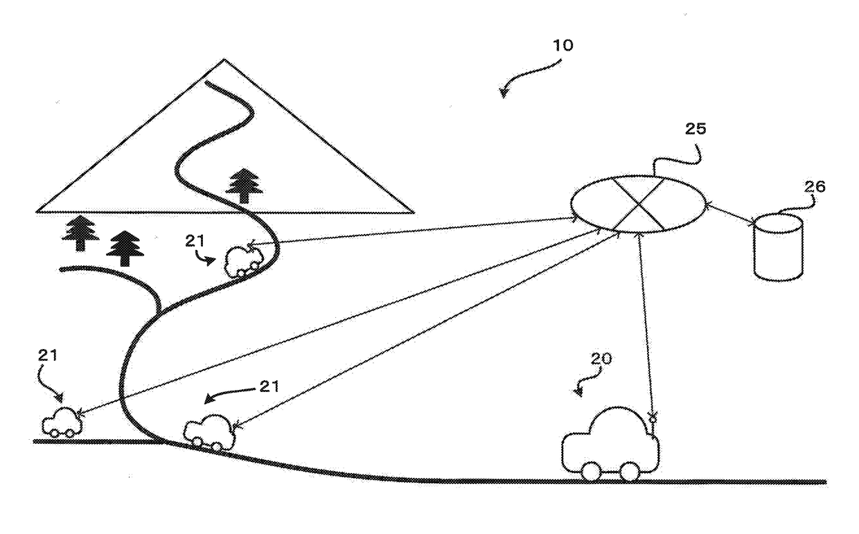
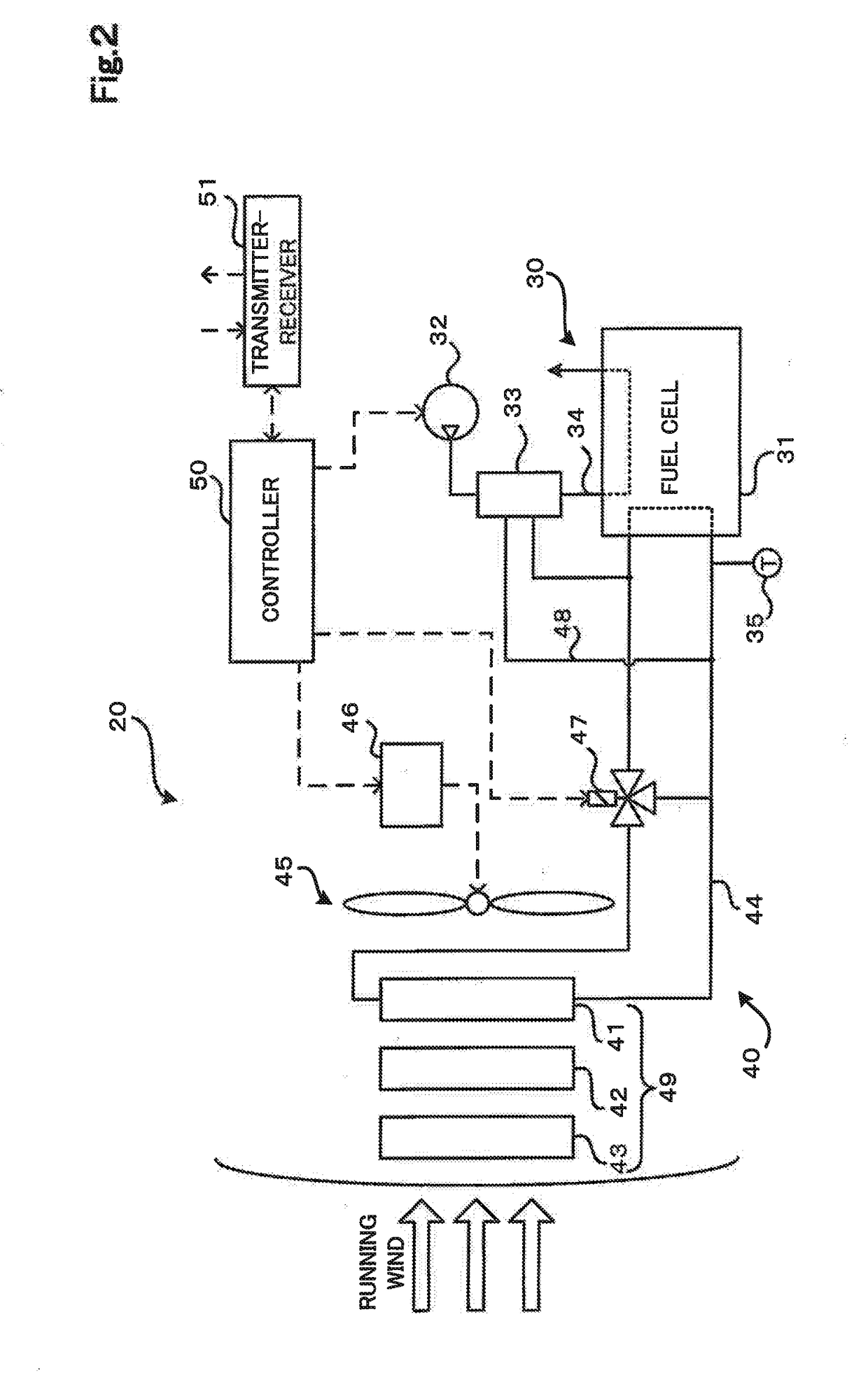
[0021]FIG. 1 is a diagram illustrating the schematic configuration of a control system 10 according to a first embodiment of the present disclosure. The control system 10 of this embodiment is provided as a control system involved in a cooling system of a fuel cell in a vehicle equipped with the fuel cell as one driving energy source. The control system 10 of the embodiment is provided as a system configured to automatically make communication with individual vehicles so as to collect information regarding the driving conditions (for example, information including positions, vehicle speeds and accelerations of the individual vehicles and navigation information) of the individual vehicles, to derive a load applied to a specific vehicle that travels on an estimated route using the collected information, and to change control of the cooling system of the fuel cell in the specific vehicle. The control system 10 automa...

second embodiment

B. Second Embodiment

[0123]The configuration of the first embodiment uses the current traffic flow information on the estimated route, in addition to the estimated route, to estimate the load applied to the own vehicle 20 during running of the own vehicle 20 on the estimated route at step S110 of FIG. 3. A different configuration may, however, be employed. A configuration that uses the past traffic flow information in place of the current traffic flow information used in the first embodiment is described below as a second embodiment. The configuration of the second embodiment is similar to the configuration of the first embodiment except a process of estimating the load applied to the own vehicle 20 during running of the own vehicle 20 on the estimated route (step S110). The description of the configuration common with the first embodiment is omitted.

[0124]According to the second embodiment, at step S430 in the overload running determination process of FIG. 7, the past average vehicl...

third embodiment

C. Third Embodiment

[0125]A configuration that uses the driving history of the own vehicle in place of the current traffic flow information used in the first embodiment at step S110 of FIG. 3 is described below as a third embodiment. The configuration of the third embodiment is similar to the configuration of the first embodiment except a process of estimating the load applied to the own vehicle 20 during running of the own vehicle 20 on the estimated route (step S110). The description of the configuration common with the first embodiment is omitted.

[0126]According to the third embodiment, at step S430 in the overload running determination process of FIG. 7, a change in average vehicle speed during past running of the own vehicle 20 on the estimated route is extracted from the driving history of the own vehicle 20, in place of estimation of the vehicle speed of the own vehicle 20 using the current traffic flow information. At step S450, a load applied to the own vehicle 20 that runs ...


PUM

PropertyMeasurementUnit
cooling poweraaaaaaaaaa
temperatureaaaaaaaaaa
heat release capacityaaaaaaaaaa

Abstract

A control method of a fuel cell vehicle comprises estimating a load applied to an own vehicle that is the fuel cell vehicle and that runs on an estimated route by using current traffic flow information or the like in addition to the estimated route; determining whether an overload area is present on the estimated route by using the estimated load; and when it is determined that the overload area is present on the estimated route, performing an increasing process of increasing a cooling power of a cooling system to be greater than a cooling power set in an ordinary control mode before the own vehicle reaches the overload area.

Description

CROSS REFERENCE TO RELATED APPLICATION[0001]The present application claims priority from Japanese patent application 2017-030851 filed on Feb. 22, 2017, the entirety of the content of which is hereby incorporated by reference into this application.BACKGROUNDField[0002]The present disclosure relates to a fuel cell vehicle and a control method thereof.Related Art[0003]A fuel cell exerts a sufficient power generation performance in a specific temperature range that is determined according to the properties of an electrolyte layer or the like and generates heat in the course of power generation. A cooling device is thus generally provided inside of the fuel cell to circulate a coolant and thereby control the temperature of the fuel cell during power generation to be in the specific temperature range.[0004]In a vehicle equipped with such a fuel cell as a driving energy source, continuation of a high-load state specifically increases the amount of power generation in the fuel cell. When t...

Claims


Application Information

Patent Timeline
Patent Type & Authority Applications(United States)
IPC IPC(8): B60L11/18H01M8/04701H01M8/04992H01M8/04007
CPCB60L11/1892H01M8/04731H01M8/04992H01M8/04074H01M2250/20B60L2240/68B60L2240/36B60L58/30B60L58/33H01M8/04H01M8/04014H01M8/04537H01M8/04701Y02E60/50Y02T10/72Y02T90/16Y02T90/40Y02T10/70
Inventor BANDAI, HIROYUKIMIZUKOSHI, TOMOHIKO
Owner TOYOTA JIDOSHA KK
Why Eureka
Try Eureka