IGBT module liquid cooling plate based on parallel liquid flow grooves and manufacturing method thereof

A liquid flow tank and liquid cold plate technology, which is applied in the direction of electrical components, electric solid devices, circuits, etc., can solve the problems of high power requirements, large temperature difference on the surface of the cold plate, and increased cost, so as to achieve good overall sealing and high flow rate. The effect of uniform distribution and good temperature uniformity

Active Publication Date: 2017-12-08
SOUTH CHINA UNIV OF TECH +1
View PDF4 Cites 11 Cited by
  • Summary
  • Abstract
  • Description
  • Claims
  • Application Information

AI Technical Summary

Problems solved by technology

The traditional flow channel has the following disadvantages: (1) In the S-type parallel single-channel or multi-channel structure, the inlet and outlet pressure loss along the way is relatively large, which will cause a large pressure drop, so the power requirement for the circulating pump of the liquid cooling system is high , the required cost increases accordingly (2) The traditional cold plate structure is likely to cause a large temperature difference on the surface of the cold plate when the inlet and outlet channels are too long, which may easily lead to uneven distribution of thermal stress and failure; (3) the traditional cold plate The structure is only designed for a certain number of IGBT modules. When the number of modules increases or decreases, the cold plate structure needs to be redesigned, which does not have good versatility

Method used


Image

  • IGBT module liquid cooling plate based on parallel liquid flow grooves and manufacturing method thereof
  • IGBT module liquid cooling plate based on parallel liquid flow grooves and manufacturing method thereof
  • IGBT module liquid cooling plate based on parallel liquid flow grooves and manufacturing method thereof

Examples


Embodiment Construction

[0033] In order to make the object, technical solution and advantages of the present invention more clear and definite, the present invention will be further described in detail below with reference to the accompanying drawings and examples. It should be understood that the specific embodiments described here are only used to explain the present invention, not to limit the present invention.

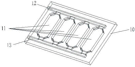
[0034] The present invention provides a kind of IGBT module liquid cooling plate based on the parallel connection of liquid flow grooves, such as figure 1 As shown, the IGBT module liquid cooling plate includes: a substrate 10 arranged on the lower end surface of the IGBT module; the upper end of the substrate 10 is provided in parallel with a plurality of liquid flow grooves 11 for cooling the IGBT module through the circulation of cooling liquid. The number of liquid flow channels in the invention is preferably 4 (of course, the number of liquid flow channels can also be other numbers)...


PUM


Abstract

The invention discloses an IGBT module liquid cooling plate based on parallel liquid flow grooves and a manufacturing method thereof. The IGBT module liquid cooling plate comprises a substrate, wherein a plurality of liquid flow grooves, for a cooling liquid to pass through, for cooling IGBT modules are formed in the upper end of the substrate in parallel; a plurality of flow deflectors for controlling the cooling liquid to be concentrated in a multi-channel region under a heating chip so as to improve the heat exchange efficiency are arranged at the positions of cooling liquid inlets of the liquid flow grooves; a liquid inlet flow passage and a liquid outlet flow passage are formed in two ends of each of the liquid flow grooves in a communicating manner respectively; a seal ring for sealing the IGBT modules is arranged above the substrate; and a cover plate for covering the substrate and the seal ring is arranged above the substrate. Through the IGBT module liquid cooling plate, the distribution of passage flow under each IGBT module is uniform, the surface of the liquid cooling plate is of good temperature uniformity, the pressure drop of inlets and outlets is controlled in a reasonable range, the heat dissipation power is high, and the overall leakproofness is good.

Description

technical field [0001] The invention relates to the heat dissipation technology of electronic devices, in particular to a liquid cold plate of an IGBT module based on parallel connection of liquid flow grooves and a manufacturing method thereof. Background technique [0002] With the increasing heat flux density of electronic device packaging, it is difficult for a single-channel cold plate structure to meet its heat dissipation requirements. For the design of mesoscale cold plate structures, multi-channel cold plate structures are increasingly favored by researchers. With the development of the new energy industry, IGBT (Insulated Gate Bipolar Transistor, insulated gate bipolar transistor or high-power switching device) has gradually been widely used as a high-power switching device. The IGBT module is mainly a package for a series of chips. The internal chips are IGBT chips and diode chips, which are often accompanied by high heat flux in the actual working process. Theref...

Claims


Application Information

Patent Timeline
Patent Type & Authority Applications(China)
IPC IPC(8): H01L23/473
CPCH01L23/473
Inventor 李东方周吉勇
Owner SOUTH CHINA UNIV OF TECH
Why Eureka
Try Eureka