Projection type video display

a video display and projection type technology, applied in the direction of projectors, color television details, instruments, etc., can solve the problems of excessive cooling light is not guided, and achieve the effect of reducing the durability of liquid crystal display panels

Active Publication Date: 2006-03-30
SANYO ELECTRIC CO LTD
View PDF3 Cites 11 Cited by
  • Summary
  • Abstract
  • Description
  • Claims
  • Application Information

AI Technical Summary

Benefits of technology

[0004] In response to a request for not projecting any image while a lamp is being turned on, it is conceivable to provide a mechanical shutter device for cutting off light from the lamp. However, in a case where the light from the lamp is cut off by the shutter device, the light is not guided to a liquid crystal display panel. Therefore, in a configuration in which the liquid crystal display panel is cooled, the liquid crystal display panel is cooled excessively when the shutter is closed. Accordingly, it is expected that durability of the liquid crystal display panel will be decreased.
[0005] In view of the above-described circumstances, it is an object of the present invention to provide a projection type video display capable of restraining an excessive cooling of a light valve caused by closing a shutter device in a configuration in which a light valve is cooled so as to prevent a decrease in durability of the light valve.
[0007] With the above-described configuration, cooling power for the light valve is decreased in a state where the shutter device is closed. Therefore, it is possible to restrain an excessive cooling of a light valve caused by closing a shutter device in a configuration in which a light valve is cooled so as to prevent a decrease in durability of the light valve.
[0010] Furthermore, in a projection type video display according to these configurations, the cooling control means may control the cooling means so as to decrease the cooling power for the light valve after a lapse of predetermined time period from a moment when the shutter device becomes a closing state. In addition, a projection type video display according to these configurations may comprise a second cooling means for air-cooling or liquid-cooling the light source. The cooling control means may control the second cooling means so as to increase cooling power for the light source in a state where the shutter device is closed.
[0011] The present invention has an effect such as restraining the excessive cooling caused by closing the shutter device in the configuration in which the light valve is cooled so as to prevent decrease in durability of the light valve.

Problems solved by technology

However, in a case where the light from the lamp is cut off by the shutter device, the light is not guided to a liquid crystal display panel.
Therefore, in a configuration in which the liquid crystal display panel is cooled, the liquid crystal display panel is cooled excessively when the shutter is closed.

Method used


Image

  • Projection type video display
  • Projection type video display
  • Projection type video display

Examples


Embodiment Construction

[0018] Hereinafter, a liquid crystal projector according to an embodiment of the present invention will be described with reference to FIG. 1 to FIG. 4.

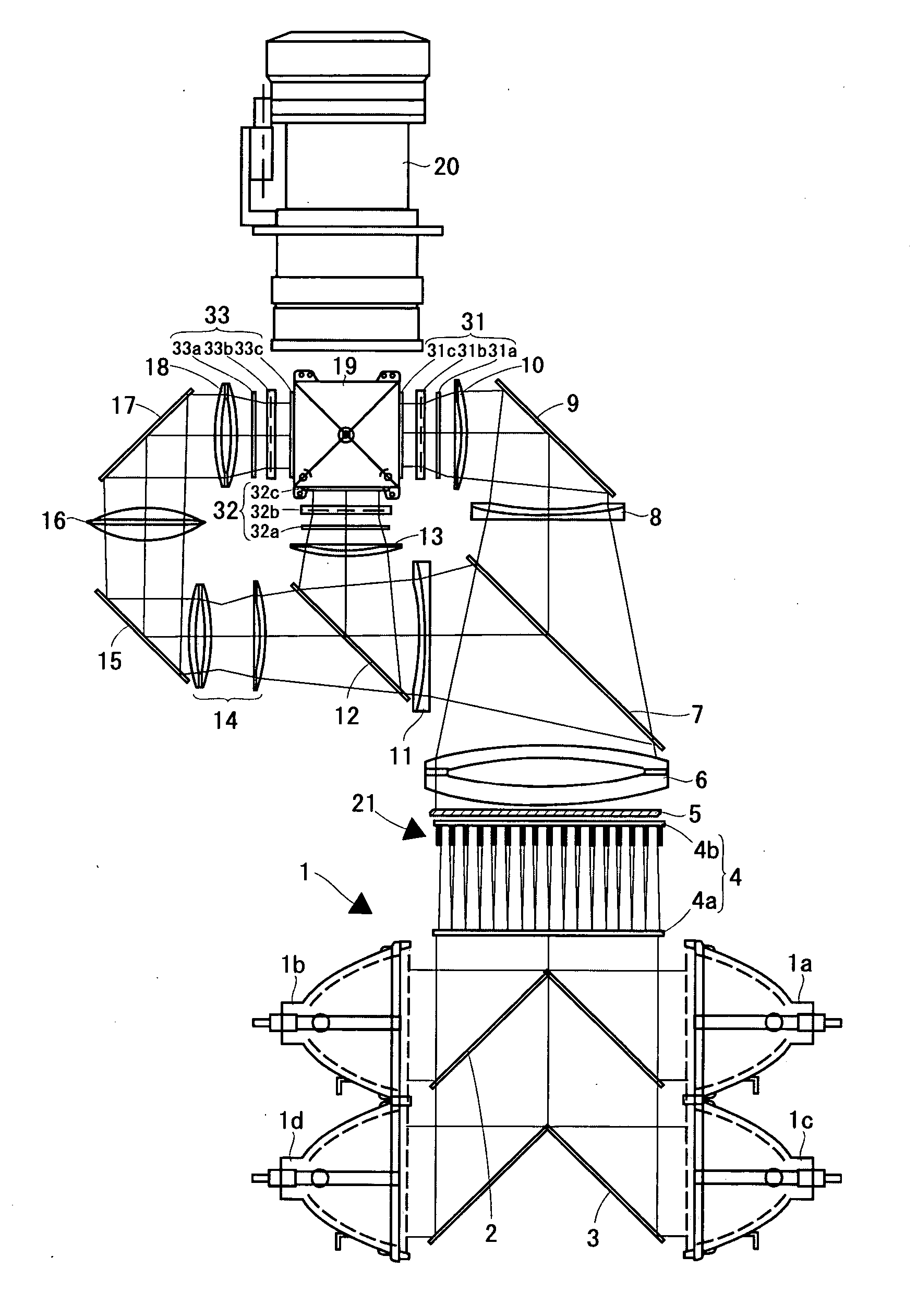
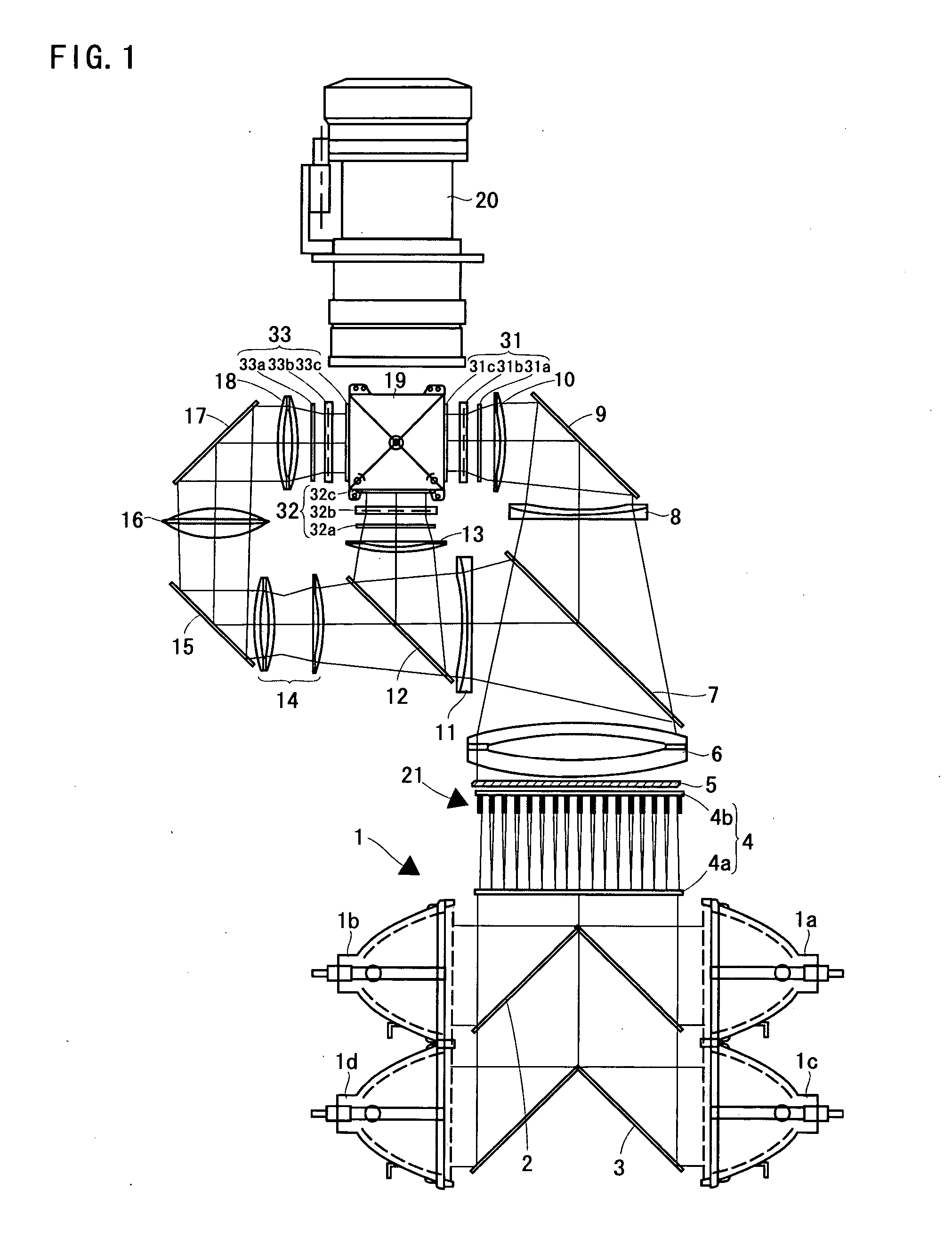
[0019]FIG. 1 is a diagram showing a four-lamp and three-panel liquid crystal projector according to this embodiment. An illuminating device 1 is formed of four lamps 1a, 1b, 1c, and 1d, mirrors 2 arranged between the lamps 1a and 1b, and mirrors 3 arranged between the lamps 1c and 1d. Each lamp is formed of an ultra-high pressure mercury lamp, a metal halide lamp, a xenon lamp, and others. Irradiating light of the lamp is emitted after being collimated by a parabolic reflector and guided to an integrator lens 4.

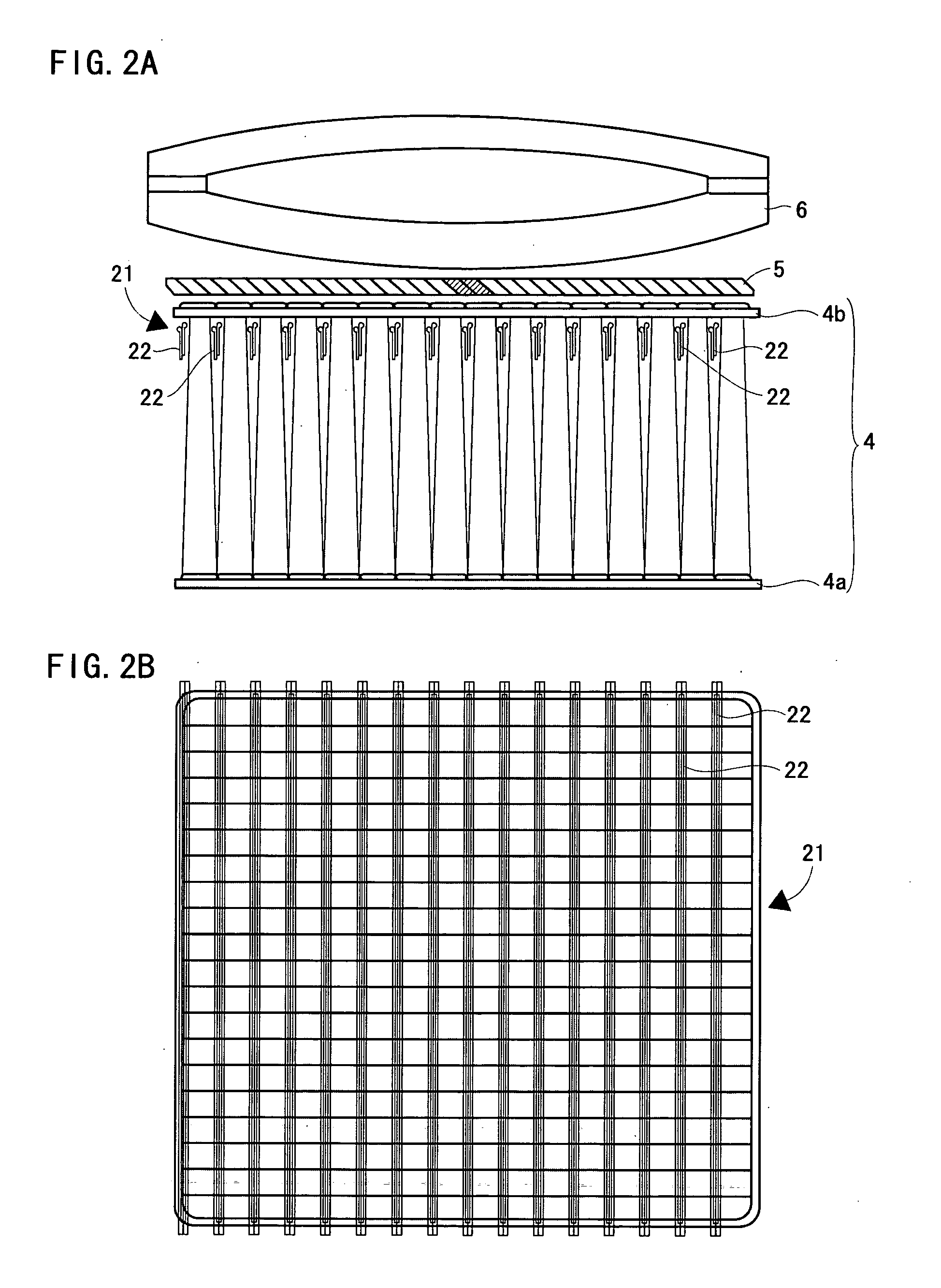
[0020] The integrator lens 4 is structured of a pair of fly's eye lenses 4a, 4b. Each pair of lenses guides light emitted from the illuminating device 1 onto an entire surface of a liquid crystal display panel described later. As a result, partial non-uniformity of luminance existing in the illuminating device 1 is evened of...


PUM


Abstract

A shutter device can switch between a state where illuminating light from a lamp of an illuminating device is blocked (referred to as a closing state of the shutter device) and a state where illuminating light passes through (referred to as an opening state of the shutter device). A system control circuit instructs a panel cooling fan-use power source to decrease a fan rotation speed, when receiving information indicating that the shutter device is in the closing state from the detecting portion. After receiving this instruction, the panel fan power source decreases power supplied to the panel cooling fan (fan motor).

Description

BACKGROUND OF THE INVENTION [0001] 1. Field of the Invention [0002] The present invention relates to a projection type video display such as a liquid crystal projector, and the like. [0003] One of methods of utilizing the liquid crystal projector is to receive a video signal output from a personal computer and to project an image. That is, when a person who makes a presentation operates a personal computer and displays the image that the person intends participants of the presentation to see on a display of the personal computer, the same image as the above-described image is projected on a screen by the liquid crystal projector, so that all the participants can see the image. On the other hand, in some cases, the person who makes a presentation may not wish to show all the images which appear in the course of operating the computer to the participants. It is noted that there is a liquid crystal projector equipped with a shutter on a light-emission side of a light source (see Japane...

Claims


Application Information

Patent Timeline
Patent Type & Authority Applications(United States)
IPC IPC(8): G03B21/16
CPCH04N9/3141H04N9/3197H04N9/315H04N9/3144
Inventor NAKAMURA, HISASHI
Owner SANYO ELECTRIC CO LTD
Why Eureka
Try Eureka