
Conditions for fluid separations in microchannels, capillary-driven fluid separations, and laminated devices capable of separating fluids

a technology of laminated devices and microchannels, which is applied in the direction of osmosis/dialysis, water/sewage treatment, combustion air/fuel air treatment, etc., can solve the problems of complex flow behavior, achieve high heat transfer rate, reduce the effect of aging and maintenance costs

Inactive Publication Date: 2005-04-05
BATTELLE MEMORIAL INST
View PDF23 Cites 60 Cited by
  • Summary
  • Abstract
  • Description
  • Claims
  • Application Information

AI Technical Summary

Benefits of technology

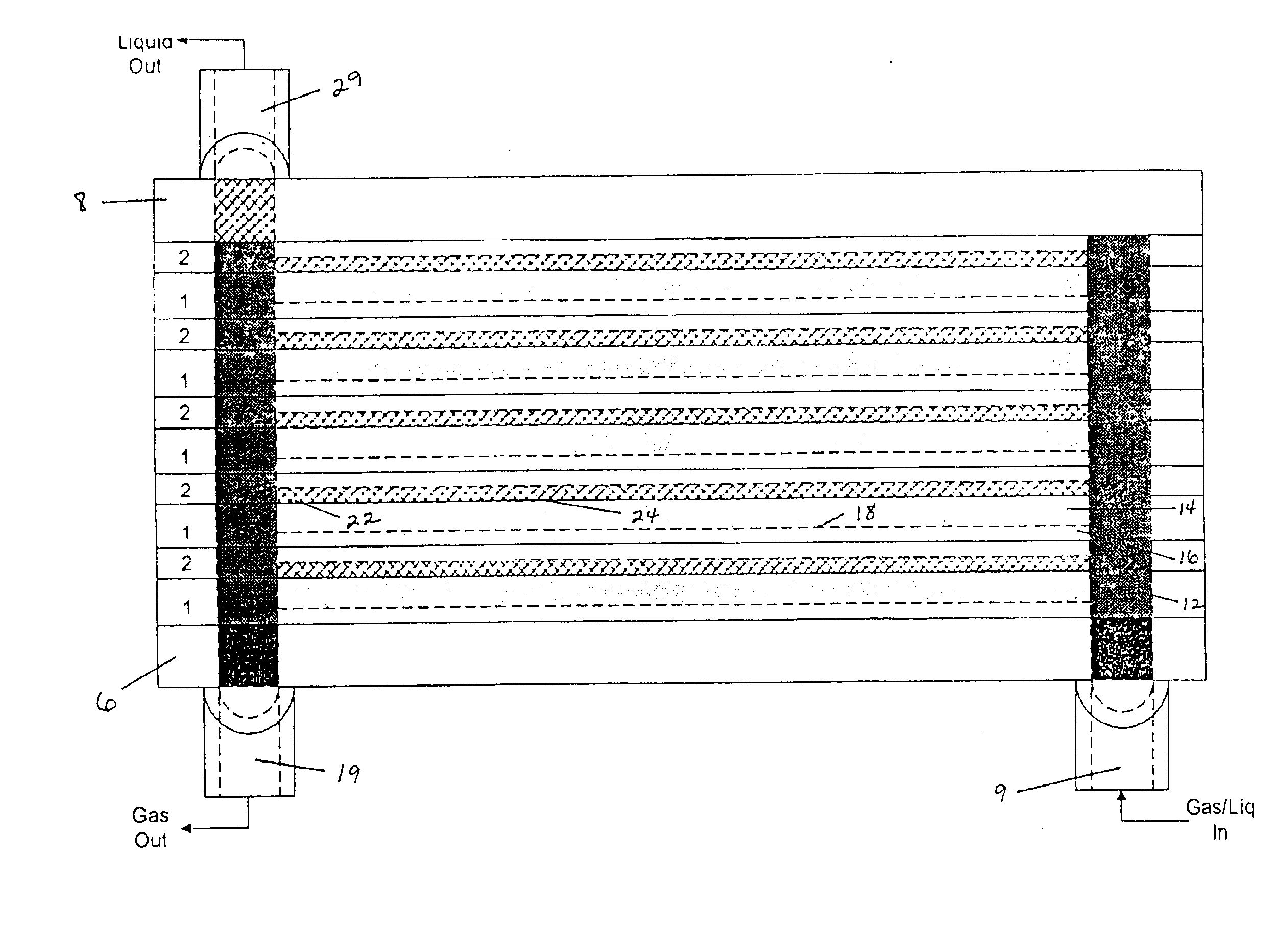
The invention, in various aspects and embodiments can provide numerous advantages including: rapid mass transport, high rates of heat transfer, low cost, durability, highly efficient gas-liquid and chemical separations in a compact space, low profile equipment, and unit process operations that function in the absence of gravity, such as in extraterrestrial applications.
Another application is a thermochemical compressor of a heat pump. If two components in the compressor have appreciable volatility, then purifying the gas stream coming from the desorber prior to the condensor can improve cycle efficiency. In preferred embodiments, a distillation column is inserted between the desorber and the condenser or integrated with the condenser.

Problems solved by technology

Phase separation technologies involve processing a multi-phase fluid stream, which can involve very complex flow behaviors.
However, the purpose of heat pipe technology is heat transfer and not mass transfer between phases.
Capillary forces have been employed in these devices to prevent mixing of the fluids, such as with a contactor plate, membrane, or by small gaps, but not for motivating fluid flow.

Method used


Image

  • Conditions for fluid separations in microchannels, capillary-driven fluid separations, and laminated devices capable of separating fluids
  • Conditions for fluid separations in microchannels, capillary-driven fluid separations, and laminated devices capable of separating fluids
  • Conditions for fluid separations in microchannels, capillary-driven fluid separations, and laminated devices capable of separating fluids

Examples


examples

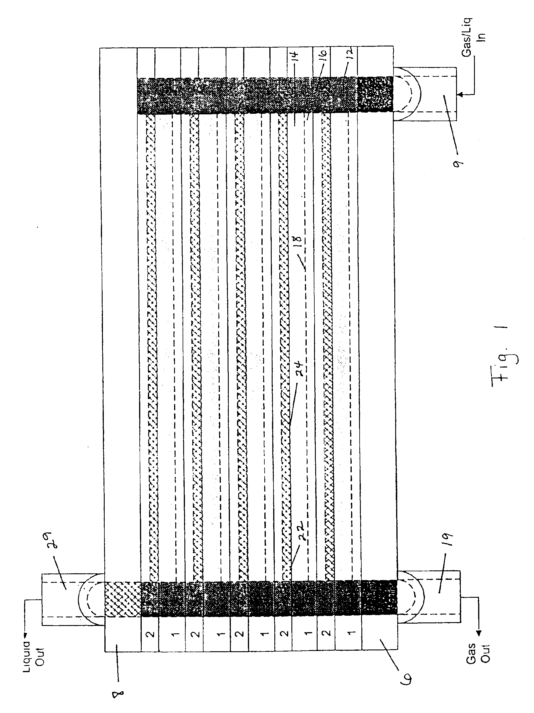
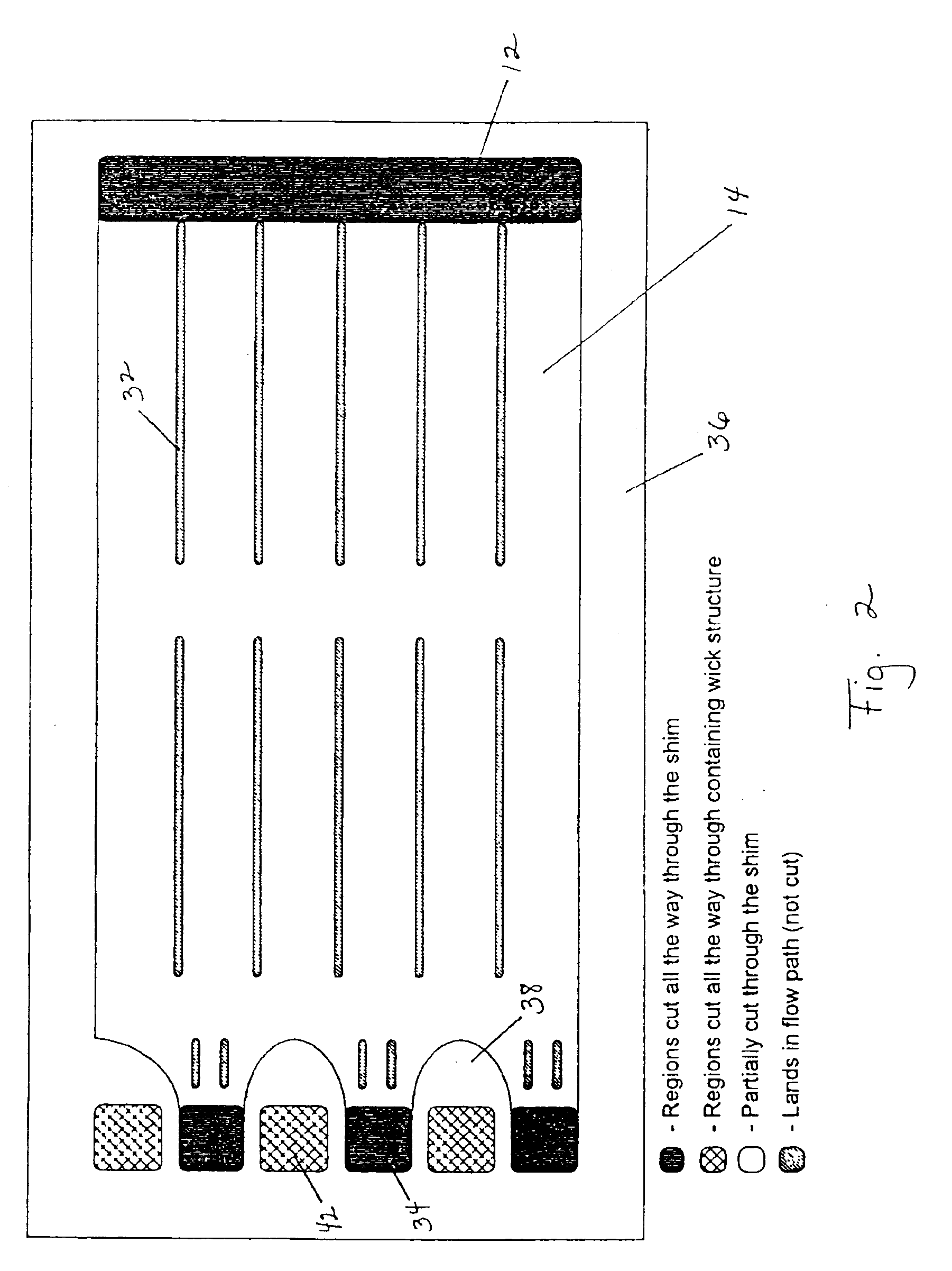
Condensation experiments were conducted in a single-channel, microchannel device. A channel was constructed that was 0.040 inch (1 mm) deep×2 cm wide×8 cm long. A 2 cm×2 cm sintered metal pore throat was placed at one end. In one set of experiments, a piece of Novex LC2001 filter paper having a dry thickness of 0.017 inch was placed in the channel as a wick, and pieces of 2 cm×2 cm 20×20 mesh stainless steel screen (McMaster-Carr) and 2 cm×2 cm 60×60 mesh screen were placed over the pore throat area to provide for a compression seal of the pore throat. In a second set of experiments, the filter paper wick was not used, instead a piece of 2 cm×8 cm 60×60 mesh screen was placed on the side of the pore throat, and a piece of 2 cm×8 cm 20×20 mesh screen placed on top. In both experiments, the channel was closed by a 0.010-inch stainless steel shim. On the other side of the steel shim, water flowed through a 0.5 cm deep×2 cm wide×6.4 cm long channel to extract heat from the condensing si...


PUM

PropertyMeasurementUnit
capillary pore sizesaaaaaaaaaa
thicknessaaaaaaaaaa
depthaaaaaaaaaa

Abstract

Methods of separating fluids using capillary forces and / or improved conditions for are disclosed. The improved methods may include control of the ratio of gas and liquid Reynolds numbers relative to the Suratman number. Also disclosed are wick-containing, laminated devices that are capable of separating fluids.

Description

FIELD OF THE INVENTIONThe present invention relates to methods of separating fluids using capillary forces and / or improved conditions for separating fluids. The invention also relates to wick-containing, laminated devices that are capable of separating fluids.INTRODUCTIONPhase separation technologies involve processing a multi-phase fluid stream, which can involve very complex flow behaviors. Two-phase flow can take many different forms, including bubbly flow, slug flow, chum flow, annular flow, and stratified flow, depending on the particular flow regime as established by the relative flow rates, fluid properties, and forces at play. See Carey, V. P., Liquid-Vapor Phase-Change Phenomena, Hemisphere Pub. Corp., Washington, 1992.A great deal of work has been performed on establishing flow maps to predict flow transitions for two-phase flow in various geometries, and seven to nine dimensionless groups have been identified as potentially important. See Mandhane, J. M., G. A. Gregory, a...

Claims


Application Information

Patent Timeline
Patent Type & Authority Patents(United States)
IPC IPC(8): B01D5/00B01B1/00B01D19/00B01J19/00B01D3/00C01B3/00C01B3/38F28D9/00B01L3/00B01D50/00B01D53/00H01M8/04
CPCB01B1/005B01D5/0003B01D19/0031B01D53/002B01J19/0093C01B3/384F28D9/005B01D3/00F28F2260/02B01J2219/00783B01J2219/00822B01J2219/00835B01J2219/00873B01J2219/00891B01J2219/00905B01J2219/00995B01L3/5027C01B2203/0805C01B2203/0833C01B2203/0233C01B2203/066B01L3/50273
Inventor TEGROTENHUIS, WARD E.STENKAMP, VICTORIA S.
Owner BATTELLE MEMORIAL INST
Learn More