Pulse tube refrigerator

a refrigerator and pulse tube technology, applied in the field of pulse tube refrigerators, can solve the problems of volume to part boil off, huge losses in natural convection, and difficult service operation, and achieve the effects of increasing the cooling power of the distributed regenerator, enhancing heat transfer, and enhancing cooling power

Inactive Publication Date: 2006-11-07
SIEMENS PLC
View PDF21 Cites 11 Cited by
  • Summary
  • Abstract
  • Description
  • Claims
  • Application Information

AI Technical Summary

Benefits of technology

[0011]The present invention seeks to provide an improved pulse tube refrigerator.
[0012]In accordance with a first aspect of the invention, there is provided a pulse tube refrigerator PTR arrangement within a cryogenic apparatus, wherein a regenerator tube of a PTR is finned. Ideally, there is a plurality of fins. The fins conveniently comprise annular discs and are spaced apart along the length of the regenerator tube. Alternatively the fins comprise outwardly directed fingers or prongs. The fins may also, comprise a single spiral arrangement. Conveniently, an associated sock surrounds all the tubes of the pulse tube, leaving only a small annular gap between the regenerator and pulse tubes and a wall of the sock. The walls of the tubes can be fabricated from materials such as thin gauge stainless steel or alloys
[0013]The invention provides a regenerator for a PTR which can act as a distributed cooler, that is to say that there is refrigeration power along the length of the regenerator. This means that the regenerator can intercept (absorb) some of the heat being conducted down the refrigerator sock (neck tube, helium column plus other elements). Whilst the absorption of this heat degrades the performance of the second stage, in one sense, this degradation is less than the heat which is extracted (intercepted) by the regenerator and therefore there is a net gain in cooling power. By placing fins along the regenerator the distributed cooling power of the regenerator is increased by enhancing the heat transfer (by increasing the surface area available for the transfer) to the helium column (and therefore the neck tube etc) that is to say, the fins or baffles, are believed to increase the surface area available for distributed heat transfer from the helium atmosphere to the regenerator.

Problems solved by technology

Any dissipation in the components or heat getting into the system causes the volume to part boil off.
This service operation is considered to be problematic by many users and great efforts have been made over the years to introduce refrigerators that recondense any lost liquid right back into the bath.
When the arrangement is tilted, natural convection sets up huge losses.
The disadvantage, however, is that the thermal contact of the coldhead at 4 K would produce a thermal impedance, which effectively reduces the available power for refrigeration.

Method used


Image

  • Pulse tube refrigerator
  • Pulse tube refrigerator
  • Pulse tube refrigerator

Examples


Embodiment Construction

[0024]There will now be described, by way of example, the best mode contemplated by the inventors for carrying out the invention. In the following description, numerous specific details are set out in order to provide a complete understanding of the present invention. It will be apparent, however, to those skilled in the art, that the present invention may be put into practice with variations from the specific embodiments.

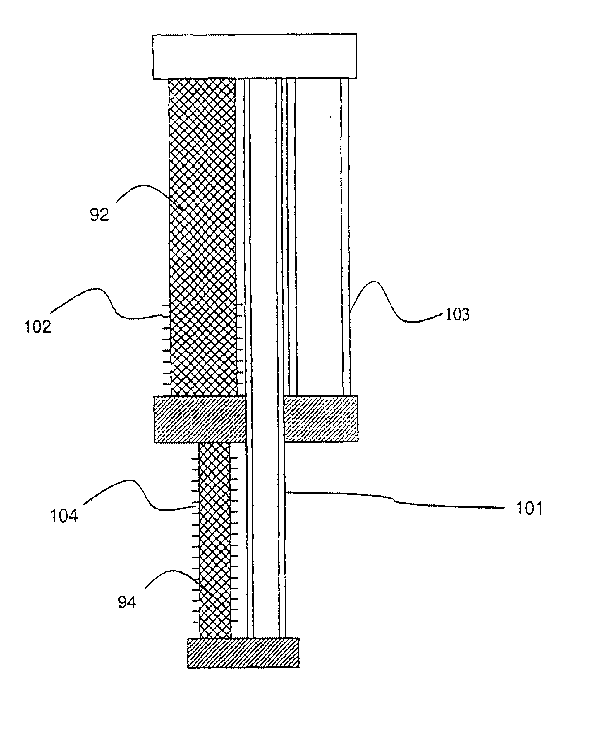
[0025]Referring now to FIG. 6, there is shown a first embodiment of the invention, wherein a 2-stage PTR arrangement 90 is shown. Regenerator tubes 92, 94 and pulse tubes 96, 98 are shown with regenerator tube 94 being finned.

[0026]FIG. 6A shows a cross-section through the regenerator tube 94 showing annular fin 104 surrounding tube 94 in the form of an annular disc. Conveniently the tube wall and the fins are manufactured simultaneously, preferably from the same material which is moderately thermally conductive, such as an austenitic stainless steel. Other materia...


PUM


Abstract

The present invention relates to pulse tube refrigerators for recondensing cryogenic liquids. In particular, the present invention relates to the same for magnetic resonance imaging systems. In many cryogenic applications components, e.g. superconducting coils for magnetic resonance imaging (mri), superconducting transformers, generators, electronics, are cooled by keeping them in contact with a volume of liquified gases (e.g. helium, neon, nitrogen, argon, methane). In a first aspect, the present invention provides a pulse tube refrigerator PTR pulse tube refrigerator (PTR) arrangement within a cryogenic apparatus, wherein a regenerator tube of the PTR is finned. In this configuration the fins or baffles, are believed to increase the surface area available for distributed heat transfer from the helium atmosphere to the regenerator.

Description

FIELD OF THE INVENTION[0001]The present invention relates to pulse tube refrigerators for recondensing cryogenic liquids. In particular, the present invention relates to the same for magnetic resonance imaging systems.BACKGROUND TO THE INVENTION[0002]In many cryogenic applications components, e.g. superconducting coils for magnetic resonance imaging (MRI), superconducting transformers, generators, electronics, are cooled by keeping them in contact with a volume of liquefied gases (e.g. Helium, Neon, Nitrogen, Argon, Methane). Any dissipation in the components or heat getting into the system causes the volume to part boil off. To account for the losses, replenishment is required. This service operation is considered to be problematic by many users and great efforts have been made over the years to introduce refrigerators that recondense any lost liquid right back into the bath.[0003]As an example of prior art, an embodiment of a two stage Gifford McMahon (GM) coldhead recondenser of ...

Claims


Application Information

Patent Timeline
Patent Type & Authority Patents(United States)
IPC IPC(8): F25B9/00F25B9/14F28F1/16F28F1/12F28F1/24F28F1/26F28F1/32F28F1/36
CPCF25B9/145F28F1/124F28F1/24F25B9/10F25B2309/1408F25B2309/1412F25B2309/1414F25B2309/1415F25B2400/17
Inventor PAN, HUAIYUHUGHES, TIMOTHYWHITE, KEITH
Owner SIEMENS PLC
Why Eureka
Try Eureka