Motor and bearing structure thereof

a technology of bearing structure and motor, which is applied in the direction of bearings, shafts and bearings, rotary bearings, etc., can solve the problems of reducing vibration and noise, and achieve the effect of reducing the inner diameter of the bearing structure, reducing the gap error, and reducing the radial shrinkage of the cover elemen

Inactive Publication Date: 2007-04-05
DELTA ELECTRONICS INC
View PDF10 Cites 11 Cited by
  • Summary
  • Abstract
  • Description
  • Claims
  • Application Information

AI Technical Summary

Benefits of technology

[0014] As mentioned above, the motor and the bearing structure thereof of the invention use the cover element in the bearing structure to cover one end of the bearing so as to form a turning portion. The turning portion has a groove as a buffer region to alleviate the radial shrinking of the cover element by shrinking of the shaft hole. This prevents the cover element from shrinking its inner diameter to touch the shaft. In other words, this feature of the invention can reduce the gap error between the cover element and the shaft. Moreover, one part of the cover element has at least one buffer structure for contacting to the side-surface of the bearing. The buffer structure provides the bearing with an anti-torque effect and a buffering effect to overcome the device and assembling errors. In comparison with the prior art, the invention also overcomes worries of a varying anti-torque of the bearing as a result of the adhesive under material and environmental changes. In addition, the buffer structure touches the bearing by a small area. The possibility of a shrinking inner diameter in the bearing structure is effectively reduced. Therefore, the cover element of the invention can indeed overcome the device and assembling errors. Moreover, the first magnetic device and the second magnetic device secure the positioning of the bearing structure, which can reduce the vibrations and noises during high-speed operations of the motor.

Problems solved by technology

Therefore, how to reduce vibrations and noises during high-speed operations is an important issue of the motor.

Method used


Image

  • Motor and bearing structure thereof
  • Motor and bearing structure thereof
  • Motor and bearing structure thereof

Examples


Embodiment Construction

[0020] The present invention will be apparent from the following detailed description, which proceeds with reference to the accompanying drawings, wherein the same references relate to the same elements.

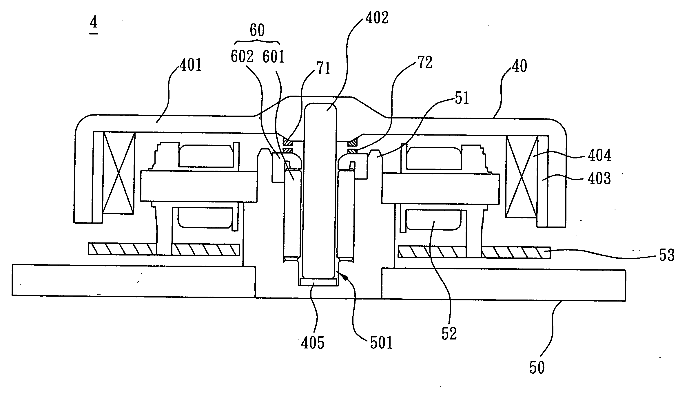
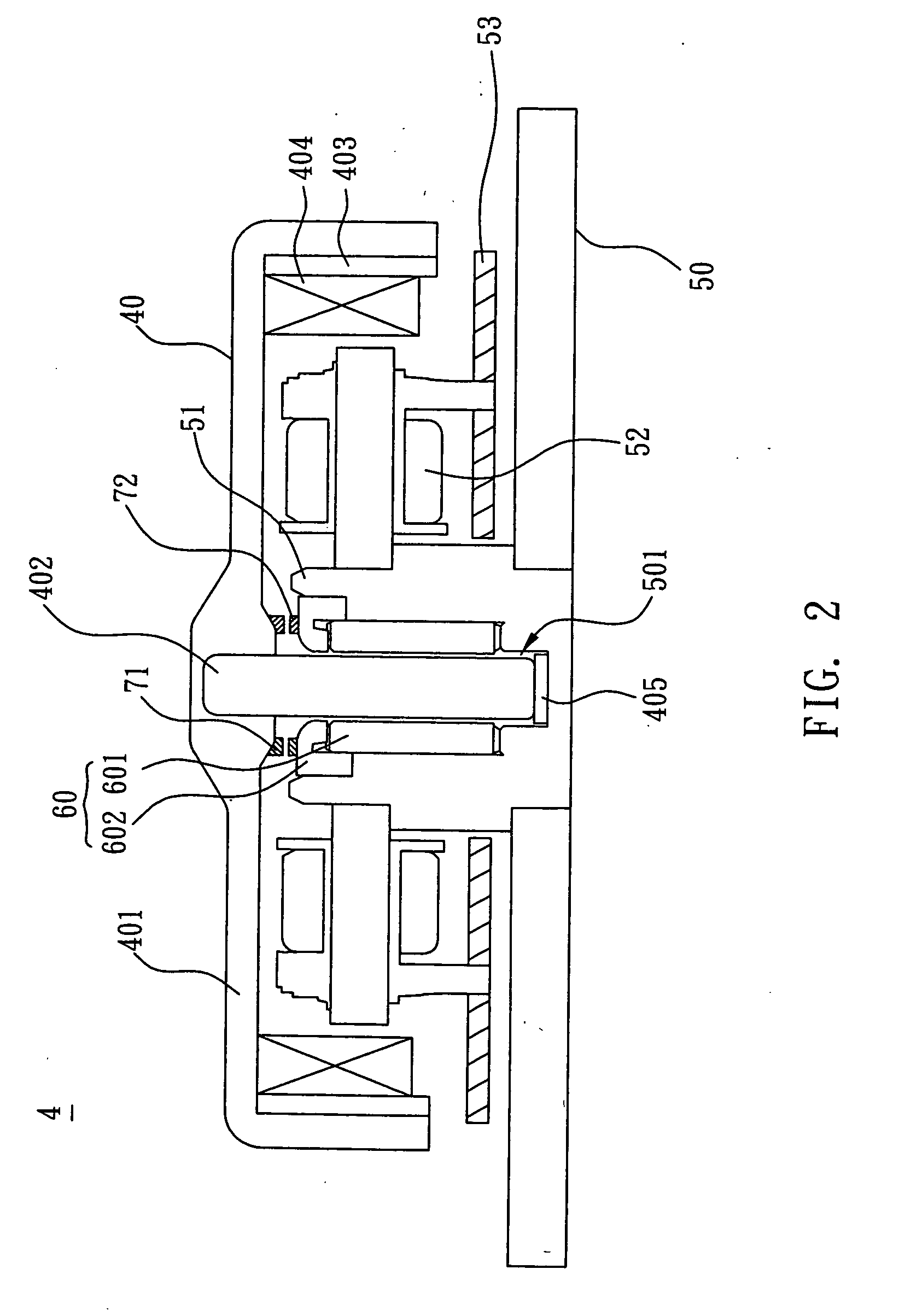
[0021] With reference to FIGS. 2 and 3, a motor 4 according to a preferred embodiment of the invention includes a rotor structure 40, a stator structure 50, and a bearing structure 60.

[0022] The rotor structure 40 includes a hub 401 and a shaft 402. The shaft 402 is connected to the hub 401. As shown in FIG. 2, the shaft 402 is embedded in the hub 401. Besides, the shaft 402 can be integrally formed with the hub 401 as a single piece.

[0023] As described above, the inner surface of the hub 401 is provided in sequence with a magnetic conductive shell 403 and a magnet 404. The magnetic conductive shell 402 is a metal chip. The magnet 404 can be a permanent magnet. In this embodiment, the magnetic conductive shell 403 and the magnet 404 have an annular structure disposed on the inner ...


PUM


Abstract

A bearing structure coupled to a shaft includes a bearing and a cover element. The cover element is held to the bearing and covers at least one portion of one end of the bearing. The cover element has a turning portion, which has a groove. A motor comprises a rotor structure, a stator structure and a bearing structure. The rotor structure has a hub and a shaft connecting to the hub. The stator structure has a hole, and the shaft is disposed in the hole. The bearing structure has a bearing and a cover element. The bearing is disposed in the shaft hole and coupled to the shaft. The cover element is held to the bearing and covers at least one portion of one end of the bearing. The cover element comprises a turning portion.

Description

BACKGROUND OF THE INVENTION [0001] 1. Field of Invention [0002] The invention relates to a motor and a bearing structure thereof and, in particular, to a motor that can overcome the element and assembling errors and a bearing structure thereof. [0003] 2. Related Art [0004] Motors have been widely used in electronic devices. As the electronic devices become smaller, the sizes of motors are also reduced while their speeds are increased. Therefore, how to reduce vibrations and noises during high-speed operations is an important issue of the motor. [0005] As shown in FIG. 1, a conventional motor 1 includes a rotor structure 10, a stator structure 20, and a bearing structure 30. The stator structure 20 drives the rotator structure 10. One shaft 101 of the rotor structure 10 is installed in a shaft hole 201 formed by a sleeve 21 of the stator structure 20. The bearing structure 30 has a bearing 301 and a cover element 302. The bearing 301 is mounted in the sleeve 21 and coupled to the sha...

Claims


Application Information

Patent Timeline
Patent Type & Authority Applications(United States)
IPC IPC(8): F16C32/06F16C33/02F16C43/00
CPCF16C17/02F16C35/02F16C35/067
Inventor TSAI, MENG-HSIUTSAI, SHANG-YEN
Owner DELTA ELECTRONICS INC
Why Eureka
Try Eureka