Capacitor module, power converter, vehicle-mounted electrical-mechanical system
Active Publication Date: 2007-05-17
HITACHI ASTEMO LTD
View PDF6 Cites 130 Cited by
Summary
Abstract
Description
Claims
Application Information
AI Technical Summary
This helps you quickly interpret patents by identifying the three key elements:
Problems solved by technology
Method used
Benefits of technology
Benefits of technology
[0012] An object of the present invention is to provide a space-saving capacitor module which has not only a connecting structure ensuring a low inductance and moderation of stresses, but also a structure suitable for cooling.
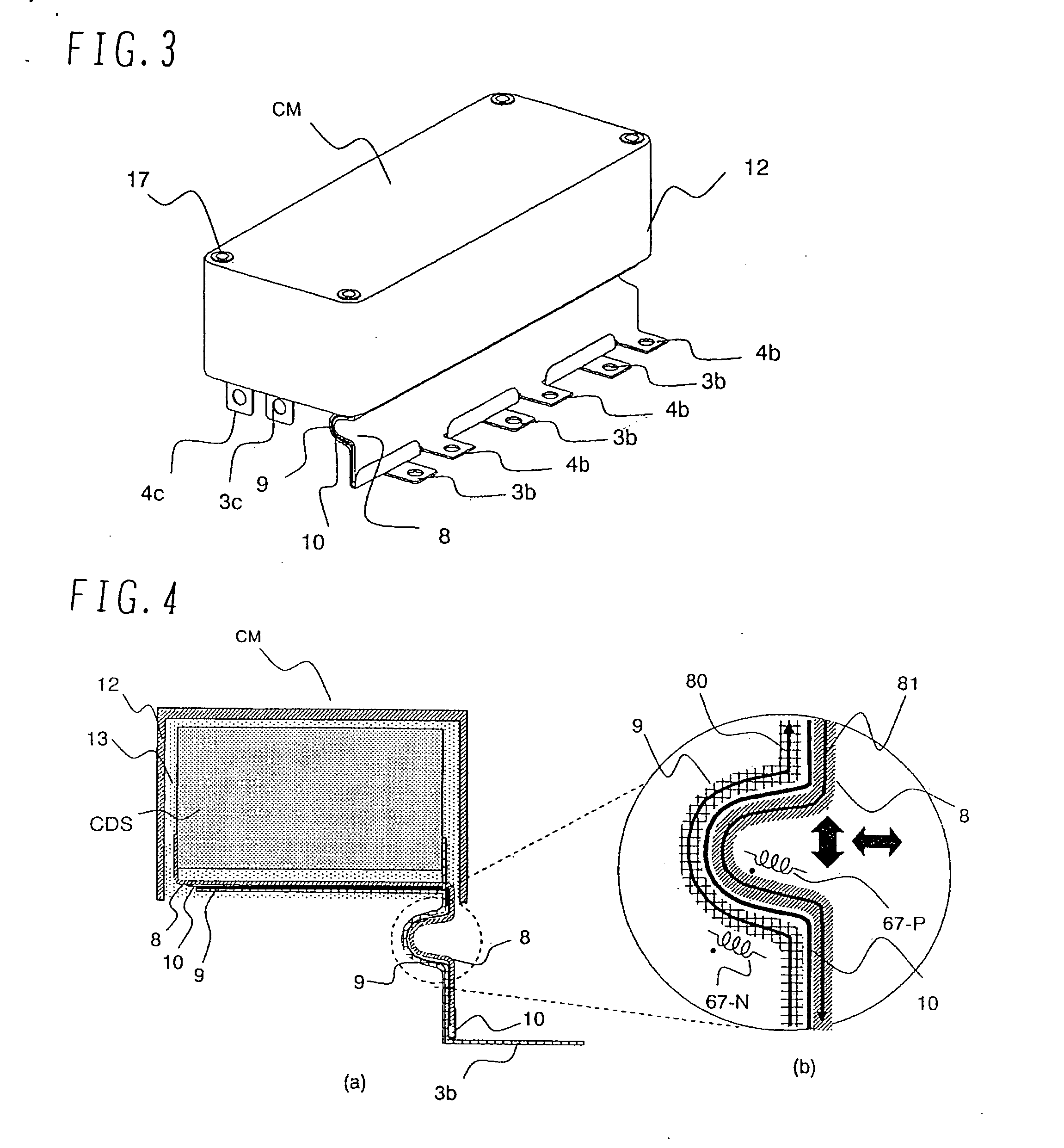
[0013] To achieve the above object, the capacitor module of the present invention is featured in reducing parasitic inductance of connecting portions. The capacitor module comprises a plurality of capacitors; and a laminate electrically connected to the plurality of capacitors and made up of a first wide conductor and a second wide conductor joined in a layered form with an insulation sheet interposed between the first and second wide conductors, the laminate comprising a first flat portion including the plurality of capacitors which are supported thereon and electrically connected thereto; a second flat portion being continuous with the first flat portion and extending at a large width in a direction away from the plurality of capacitors supported on the first flat portion; and connecting portions formed at ends of the first flat portion and the second flat portion and electrically connected to the exterior.
[0019] Thus, according to the present invention, the capacitor module can be obtained which has the connecting structure ensuring a low inductance and moderation of stresses and which is suitable for reducing a surge voltage caused at the time of switching in the power converter. The power converter having a small size and a high power density can also be obtained by using the capacitor module, and the vehicle-mounted electrical-mechanical system can further be obtained by using the power converter.
Problems solved by technology
However, a capacitor module constructed by combining a plurality of capacitors with each other is large and weight.
Accordingly, when the capacitors are connected in proximity relation as in the known techniques, stresses are concentrated in an electrically connecting portion, thus causing rupture in, e.g., an environment of severe temperature difference within an inverter for the HEV and an environment of severe vibration encountered when the HEV is driven over a road block or other level differences in roads.
Such a solution, however, increases inductance in the connecting portion and cannot realize a sufficient reduction of inductance.
In addition, because the capacitors and the power semiconductor module are arranged side by side on a plane, the known techniques are not suitable for satisfying requirements demanded in the inverter for the HEV, i.e., space-saving installation, wiring with a low inductance, and a layered structure in which the capacitors are installed over the power semiconductor module.
Method used
Image
Click on the blue label to locate the original text in one second.
Reading with bidirectional positioning of images and text.
Examples
first embodiment
[0043] A capacitor module, a power converter, and a vehicle-mounted electrical-mechanical system according to the present invention will be described below with reference to FIGS. 1-12.
[0044] In the following embodiment, a vehicle-mounted power converter is described, by way of example, as the power converter in which is employed the capacitor module of the present invention.
[0045] The construction described below is also applicable to DC-DC power converters, such as a DC / DC converter and a DC chopper. Further, the construction described below is applicable to power converters used for industrial and domestic purposes.
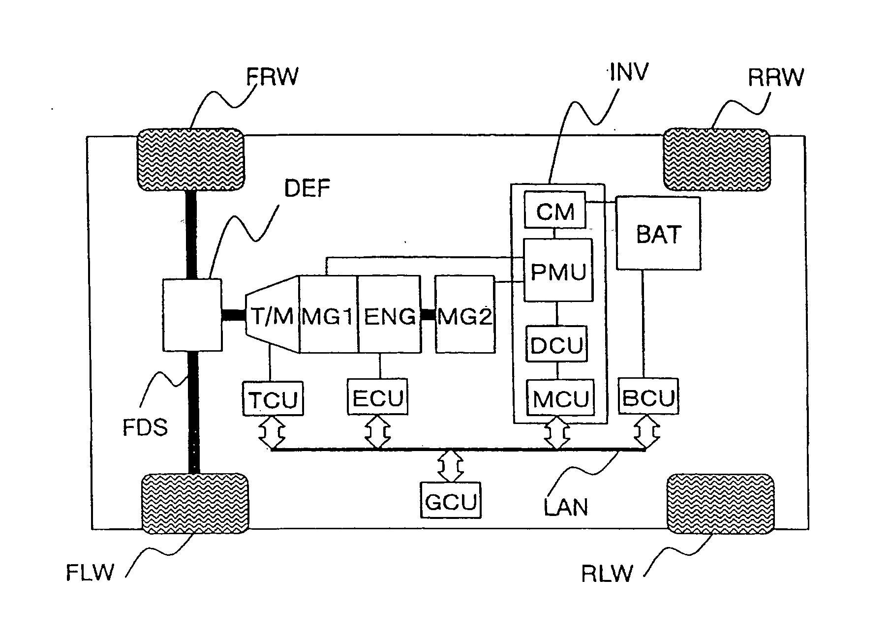
[0046]FIG. 1 is a block diagram of a hybridelectric vehicle (HEV) in which a vehicle-mounted electrical-mechanical system constructed of a power converter INV using the capacitor module according to the first embodiment of the present invention is combined with an internal combustion enginesystem.
[0047] The HEV to which is applied this first embodiment includes fr...
second embodiment
[0143] The construction of a capacitor module CM and a power converter INV according to the present invention will be described below with reference to FIGS. 13-20.
[0144] This second embodiment enables, in the motor system shown in FIG. 1, the power converter INV for controlling two motors MG1 and MG2 to be realized with a low inductance, a stress moderating structure and a smaller size.
[0145]FIG. 13 is a perspective view showing the construction of each capacitor module according to the second embodiment of the present invention. FIG. 14 is a plan view showing the arrangement of each power module according to the second embodiment of the present invention. FIGS. 17A and 17B are each a sectional view showing the power converter according to the second embodiment of the present invention. FIG. 18 is a circuit diagram showing the entire construction of the power converter INV according to the second embodiment of the present invention. Note that, in those drawings, the same character...
third embodiment
[0184] The construction of a capacitor module according to the present invention is shown in FIG. 21.
[0185]FIG. 21 is an exploded perspective view showing the construction of a capacitor module according to a third embodiment of the present invention. Note that, in FIG. 21, the same characters as those in FIG. 4 denote the same parts.
[0186] In this third embodiment, the basic construction of a capacitor module CM is the same as that of the capacitor module CM shown in FIGS. 4-10. However, the U-shaped bent structure, shown in FIG. 4, is not provided in the second flat portion of each of the layered wide conductors 8 and 9.
[0187] According to this third embodiment, although the effect of moderating stresses in the connecting portion is not so expected as the case including the bent structure, a certain effect of moderating stresses and reducing inductance can be realized because led-out portions of the wide conductors are in the layered form.
PUM
Abstract
A capacitor module in which the structure of a connecting portion is highly resistant against vibration and has a low inductance. The capacitor module includes a plurality of capacitors and a laminate made up of a first wide conductor and a second wide conductor joined in a layered form with an insulation sheet interposed between the first and second wide conductors. The laminate comprises a first flat portion including the plurality of capacitors which are supported thereon and electrically connected thereto, a second flat portion continuously extending from the first flat portion while being bent, and connecting portions formed at ends of the first flat portion and the second flat portion and electrically connected to the exterior.
Description
BACKGROUND OF THE INVENTION [0001] 1. Field of the Invention [0002] The present invention relates to a capacitor module, a power converter, and a vehicle-mounted electrical-mechanical system. [0003] 2. Description of the Related Art [0004] Recently, a power semiconductor device capable of switching a large current has been developed. A power converter using such a power semiconductor device is able to supply electric power to a load, e.g., a motor, with high efficiency through the switching. Therefore, the power semiconductor device is widely utilized for driving motors of vehicle-mounted electrical-mechanical systems in trains, automobiles, etc. In a hybridelectric vehicle (HEV), particularly, an engine and an electric motor are combined with each other to realize outputting of higher torque from low rotation speed of the motor, storage of regenerative energy into a battery, as well as higher fuel economy and a reduction of CO2 in cooperation with an idle stop system (automatic en...
Claims
Application Information
Patent Timeline
Application Date:The date an application was filed.
Publication Date:The date a patent or application was officially published.
First Publication Date:The earliest publication date of a patent with the same application number.
Issue Date:Publication date of the patent grant document.
PCT Entry Date:The Entry date of PCT National Phase.
Estimated Expiry Date:The statutory expiry date of a patent right according to the Patent Law, and it is the longest term of protection that the patent right can achieve without the termination of the patent right due to other reasons(Term extension factor has been taken into account ).
Invalid Date:Actual expiry date is based on effective date or publication date of legal transaction data of invalid patent.

