De-icing system for traffic signals

a traffic signal and deicing technology, applied in lighting applications, roads, instruments, etc., can solve the problems of reducing the inherent benefit of incandescents, melting most, if not all, snow and ice on the lenses of incandescent traffic signals, etc., to reduce power consumption, reduce heat dissipation, and reduce power consumption

Inactive Publication Date: 2007-05-24
MFR & TRADERS TRUST +1
View PDF11 Cites 26 Cited by
  • Summary
  • Abstract
  • Description
  • Claims
  • Application Information

AI Technical Summary

Benefits of technology

[0005] The present invention is directed to a circuit that detects and eliminates the buildup of frozen matter, such as snow or ice, on the viewable face or lens of an LED traffic signal. The circuit of the present invention monitors the ambient temperature within the traffic signal, and when the temperature falls below a certain set point where snow and / or ice accumulation can occur, the circuit begins looking for the buildup of snow and / or ice on the lens of the traffic signal. When the circuit detects the buildup of frozen matter, the circuit “warms” the face or lens of the traffic signal so as to defrost, and thereby eliminate, the frozen matter buildup. The circuit of the present invention uses a heating element or a plurality of elements that are mounted on, or in proximity to, the face or lens of the LED traffic signal to warm the face or lens of the signal. The heating elements are activated only when a sensor detects the buildup of frozen matter on the lens of the signal. The heating elements can be any device that produces heat when power is applied to them. Preferably, the heating elements are a plurality of high wattage resistors.
[0006] The circuit of the present invention includes a microcontroller that monitors ambient temperature within the LED traffic signal using an internal sensor. If the ambient temperature is above a temperature set point where ice and / or snow can form, the microcontroller takes no action. If the ambient temperature is below the set point, the microcontroller begins looking for the build-up of ice or snow on the lens of the LED traffic signal. Using an internal analog-to-digital converter that receives a signal from a photodiode light sensor, the microcontroller measures the ambient light level external to the signal. The measure of ambient light is used by the microcontroller as a baseline to reduce or eliminate false triggering of the circuits used to detect the buildup of ice or snow due to external light sources, such as sunlight, street lights, etc.

Problems solved by technology

The large amount of power used by incandescent traffic signals was converted to heat and dissipated through the face or lens of the traffic signal, resulting in the melting of most, if not all, snow and ice on the lenses of the incandescent traffic signals.
However, this significant improvement in power efficiency provided by the LED traffic signals eliminated the inherent benefit of the incandescent signals to reduce or eliminate the buildup of frozen snow and / or ice on the lenses of the traffic signals.
This dangerous buildup of snow and / or ice on the LED signals has caused many accidents, and is a major concern for the safety of the motoring public.

Method used


Image

  • De-icing system for traffic signals
  • De-icing system for traffic signals
  • De-icing system for traffic signals

Examples


Embodiment Construction

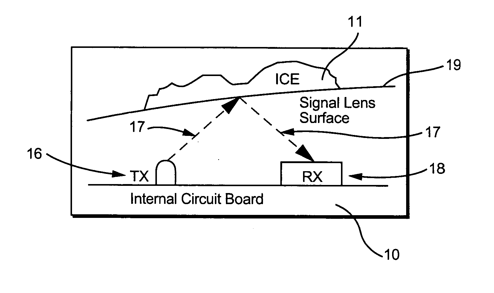
[0017] The present invention is directed to a circuit 10 for detecting the buildup of snow and / or ice on the lens of an LED traffic signal and for eliminating the buildup of the snow and / or ice from the lens of an LED traffic signal.

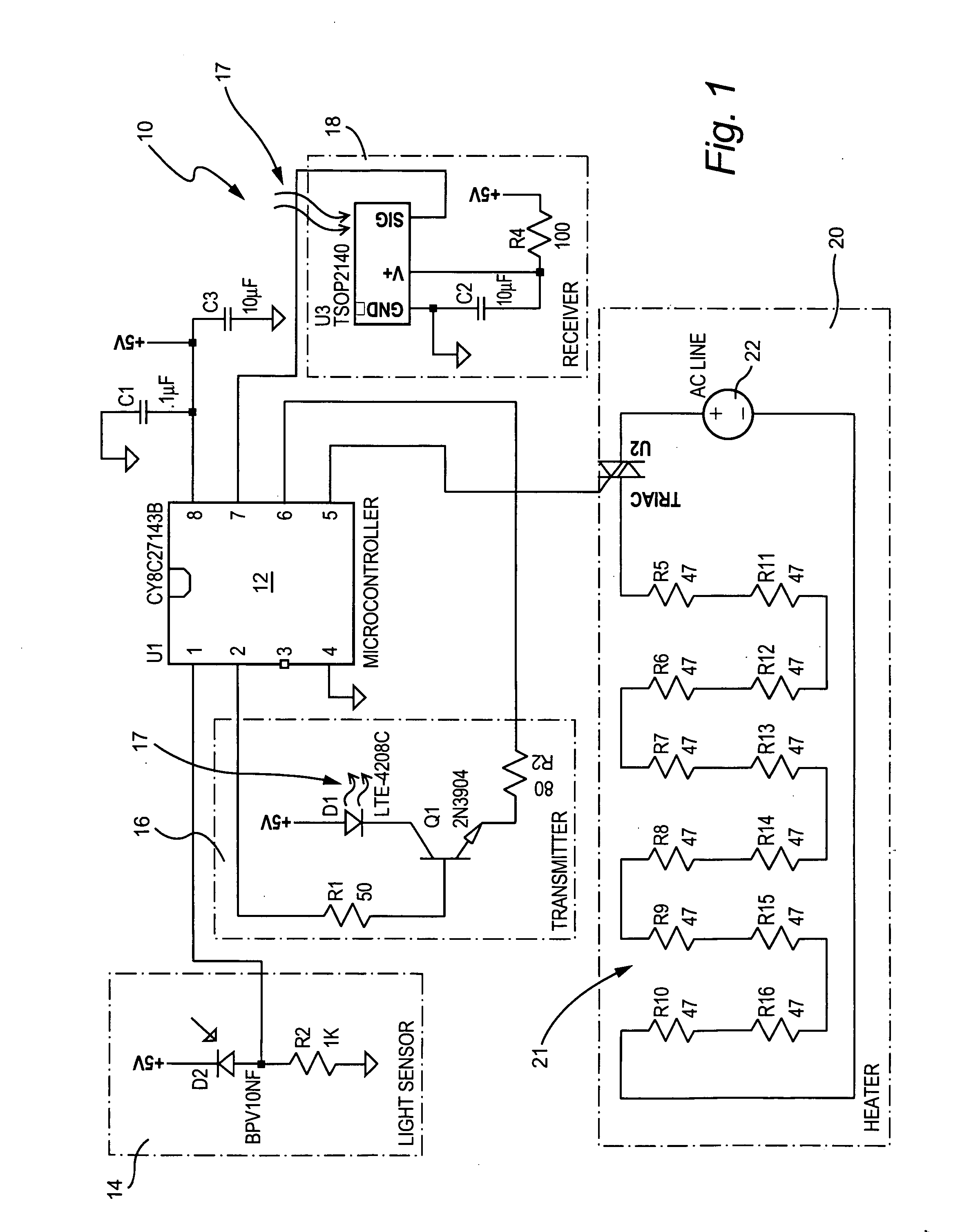
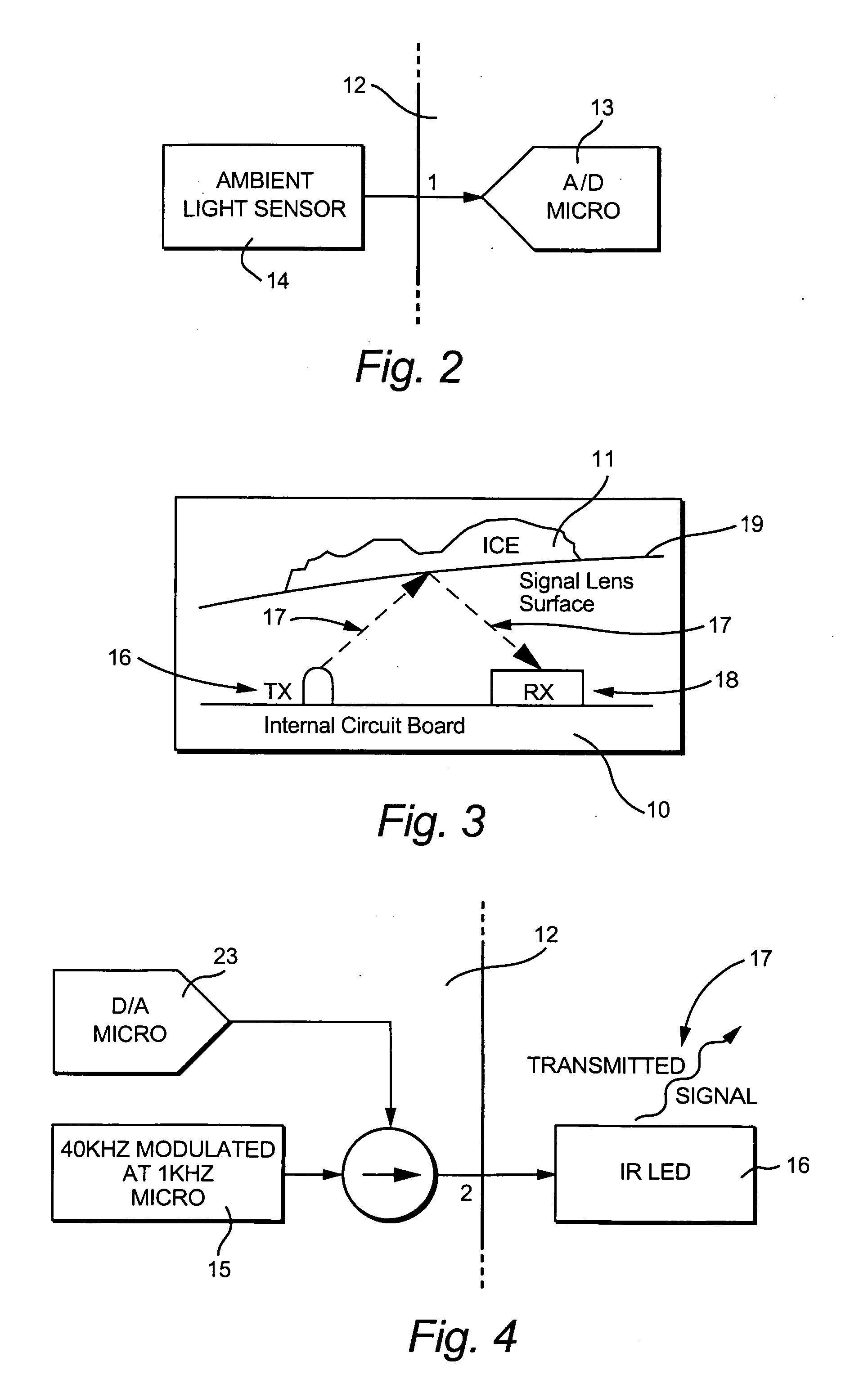
[0018] The heart of circuit 10 is a microcontroller 12, which senses ambient temperature within the LED signal, initiates the function of looking for snow and / or ice buildup when the ambient temperature falls below a certain set point and initiates the operation of a heater to eliminate ice and / or snow when it is detected. Preferably, microcontroller 12 is a CY8C27143B programmable microcontroller manufactured, for example, by Cypress Semiconductor Corp. Microcontroller 12 is shown as component U1 in the schematic of circuit 10 shown in FIG. 1, which includes an internal sensor to monitor the temperature within the LED signal.

[0019] As shown in FIGS. 1 and 2, the circuit 10 also includes an ambient light sensor circuit 14, which uses a light sensing ph...


PUM


Abstract

A circuit is disclosed for detecting and eliminating the buildup of snow and / or ice on the viewable face of an LED traffic signal lens. The circuit measures the ambient temperature within the LED signal, and when the temperature falls to a level where snow and / or ice accumulation can occur, the circuit begins looking for snow and / or ice buildup on the lens of the LED signal. An infrared LED transmits a signal which is reflected when snow or ice is present on the lens of the traffic signal. When the reflected signal is received by an infrared receiver, it sends a signal to a microcontroller, which analyzes the signal to determine if it is a valid signal. If it is, a heater is turned on until the ice and snow are removed.

Description

[0001] The present invention relates to LED traffic signals, and, more particularly, to a circuit for detecting and eliminating the buildup of snow and ice on the lenses of LED traffic signals. SUMMARY OF THE INVENTION [0002] Before light emitting diode (“LED”) traffic signals began replacing traffic signals using incandescent bulbs, the buildup of frozen matter, such as snow and ice, on the viewable faces or lenses of incandescent traffic signals was not an issue. Typically, the incandescent signals required an amount of power that was much larger than that required by LED traffic signals. The large amount of power used by incandescent traffic signals was converted to heat and dissipated through the face or lens of the traffic signal, resulting in the melting of most, if not all, snow and ice on the lenses of the incandescent traffic signals. [0003] With the introduction of LED traffic signals, a significant reduction in power consumption over that used by incandescent signals was ...

Claims


Application Information

Patent Timeline
Patent Type & Authority Applications(United States)
IPC IPC(8): H05B1/02
CPCE01F9/007F21V29/90F21W2111/00E01F9/40F21W2111/02F21Y2115/10
Inventor SMITH, DAVIDCANAN, STEVEN
Owner MFR & TRADERS TRUST
Why Eureka
Try Eureka