Vehicle collision detector

Active Publication Date: 2007-06-07
CALLAHAN CELLULAR L L C
View PDF13 Cites 2 Cited by
  • Summary
  • Abstract
  • Description
  • Claims
  • Application Information

AI Technical Summary

Benefits of technology

[0010] The collision prevention detector also encompassing a blind spot detector (BSD) presents a solution that provides a secure and precise warning device to a vehicle driver for perception of other vehicles in front of the vehicle, when reversing the vehicle and in the blind spot area so that accidents can be avoided.

Problems solved by technology

This means that approximately 800.000 accidents in the western world are related to this cause every year.
Impacts of this category, diagonally from behind and by surprise cause serious damage to vehicle passengers traveling in the cars involved in accidents.
A lack of vision in the dead angle or blind spot is a serious traffic and security problem, which up to date has not been presented a technically satisfactory solution.
The course of events, when a vehicle is impacted from behind, laterally or diagonally is often causing serious damage to passengers.
These types of impacts conventionally cause a rotation movement which in its turn often dislocates the driver and passengers from their normal position in the seats and hence diminish effects from seat-belts and airbags.
This leads to risks for severe damage and high risks for disabilities and paralysis.
Although, the blind spot or the dead angle still constitutes a problem.
Solutions introduced up to now have not achieved a clear cut aid for specific detection of other vehicles in for instance the blind spot.
Some of the solutions are technically too complicated and hence too expensive to be attached as a feature on standard vehicles.
Spherical mirrors or divided mirrors have not provided the desired results either.
An overlapping, interfering or unclear information will only confuse, cause doubts and eventually an erratic maneuver by the driver, e.g., two images of the same vehicle.
A device that provides warning signals for vehicles clearly seen in the rear mirror, will eventually on one hand create false positives.
On the other hand there is a risk that a device with longer detection area will diminish the frequency of looking in the mirrors, since drivers eventually will rely on the warning device.
This will increase risks and deteriorate traffic security rather than improve security.
Systems utilized for preventing collision, include those using video camera detection, which suffer sever drawbacks by not being able to measure distances.

Method used


Image

  • Vehicle collision detector
  • Vehicle collision detector
  • Vehicle collision detector

Examples


Embodiment Construction

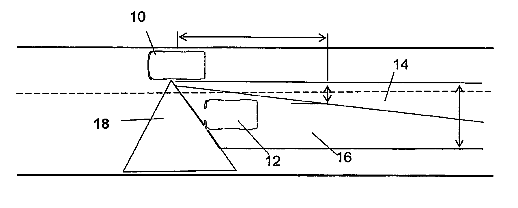
[0035] During development of the present invention the conclusion has been established that a blind spot warning device should be strictly limited to the blind spot and its nearest surrounding in order to fulfill the requirement of a safety device. An uncomplicated technology with low risk of failure, easy to adapt in different mirror housings, headlights, rear lights, or any other suitable position on a vehicle with a low cost would be appreciated as provided by the present invention. Moreover, it provides clear cut detection in the blind spot overcoming false positives, doubtful images, and providing an instant warning through a simple function with a clear message: WARNING! There is something in the Blind Spot, DO NOT TURN!

[0036] Prototypes of the present invention have been tested with excellent results. But there is a lack of specific statistics on blind spot related accidents, and it does not exist in official statistics. The detector of the present invention is supplementary,...


PUM


Abstract

A collision prevention detector (22), and a method therefor, to be mounted on a vehicle (10), transmits a sequence of transmissions of IR signals. The signals are transmitted in sequences alternating between at least one at the right and to the left positioned LED (24, 26, 34, 36), when both signals provide a return / reflected signal to IR-receiver an object (12) is determined as present within the area / zone from the point where the transmitted signals intersect / cross. Sequencing of signals makes it possible to position a return signal from an object (12), as one of the signals has to confirm the other signal to provide a warning signal. Moreover, a first set of LED's detects objects in a near-field zone (40) of the vehicle, and a second set detects objects beyond the first field in a far-field zone (42), whereby at least two sets of the LED's are positioned to the right and to the left.

Description

TECHNICAL FIELD [0001] The present invention pertains to a collision prevention detector and a method therefore, to be mounted on a vehicle, transmitting a sequence of transmissions of IR signals. The signals are transmitted in sequences alternating between at least one at the right and to the left positioned LED, when both signals provide a return / reflected signal to an IR receiver an object is determined as present within the area / zone from the point where the transmitted signals intersect / cross. A sequencing of signals makes it possible to position a return signal from an object or vehicle, as one of the signals has to confirm the other signal to provide a warning signal. BACKGROUND ART [0002] Statistics show that approximately 20% of all accidents are related to lack of vision in the “Dead Angle” or “Blind Spot” of a vehicle. This means that approximately 800.000 accidents in the western world are related to this cause every year. Impacts of this category, diagonally from behind...

Claims


Application Information

Patent Timeline
IPC IPC(8): B60Q1/00G01S17/931G01S17/87G01V8/20
CPCG01S7/4811G01S7/4813G01S7/4814G01S17/87G01S17/936G01S2013/9332G01V8/20G01S2013/9315G01S17/931
Inventor SJONELL, GORAN
Owner CALLAHAN CELLULAR L L C
Why Eureka
Try Eureka