Diversity receiving device

Active Publication Date: 2007-06-07
SOCIONEXT INC
View PDF6 Cites 13 Cited by
  • Summary
  • Abstract
  • Description
  • Claims
  • Application Information

AI Technical Summary

Benefits of technology

[0018] According to the aspect of the invention of the invention, since the power supply to the systems other than the se

Problems solved by technology

In general, power consumption of th

Method used


Image

  • Diversity receiving device
  • Diversity receiving device
  • Diversity receiving device

Examples


first embodiment

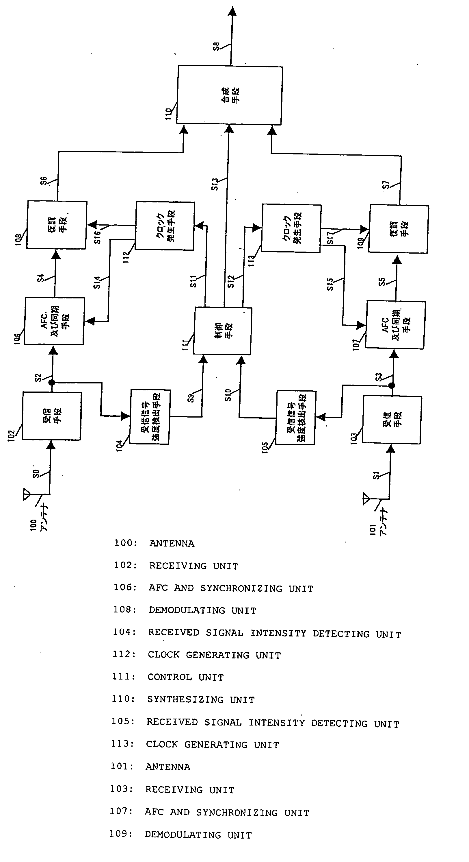
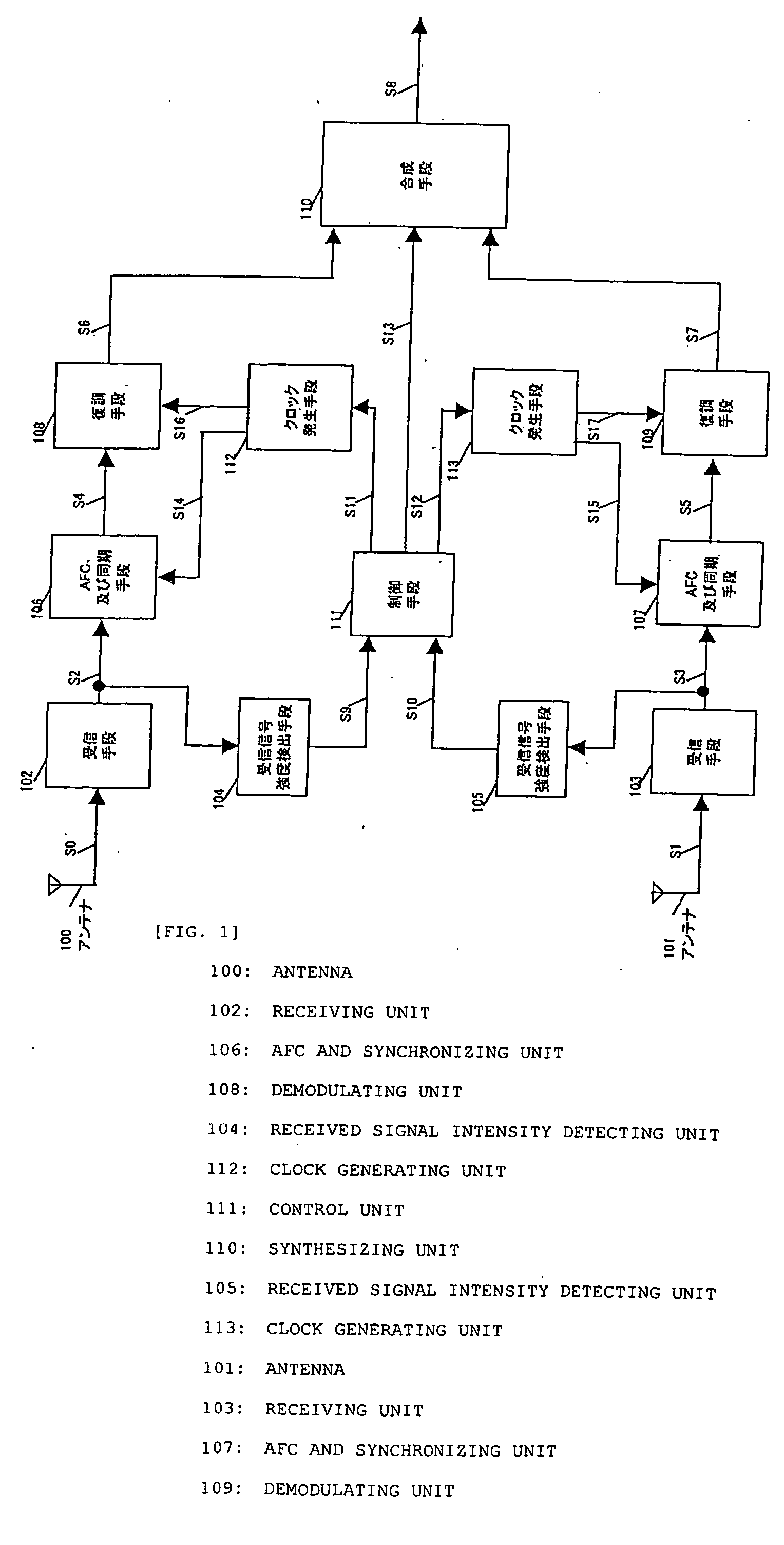
[0036]FIG. 1 is a block diagram showing the configuration of a diversity receiving device according to a first embodiment of the invention. In FIG. 1, reference numeral 100 denotes a first antenna, reference numeral 101 denotes a second antenna, reference numeral 102 denotes a receiving unit of a first system, reference numeral 103 denotes a receiving unit of a second system, reference numeral 104 denotes a received signal intensity detecting unit of the first system, reference numeral 105 denotes a received signal intensity detecting unit of the second system, reference numeral 106 denotes an AFC and synchronizing unit of the first system, reference numeral 107 denotes an AFC and synchronizing unit of the second system, reference numeral 108 denotes a demodulating unit of the first system, reference numeral 109 denotes a demodulating unit of the second system, reference numeral 110 denotes a synthesizing unit, reference numeral 111 denotes a control unit, reference numeral 112 deno...

second embodiment

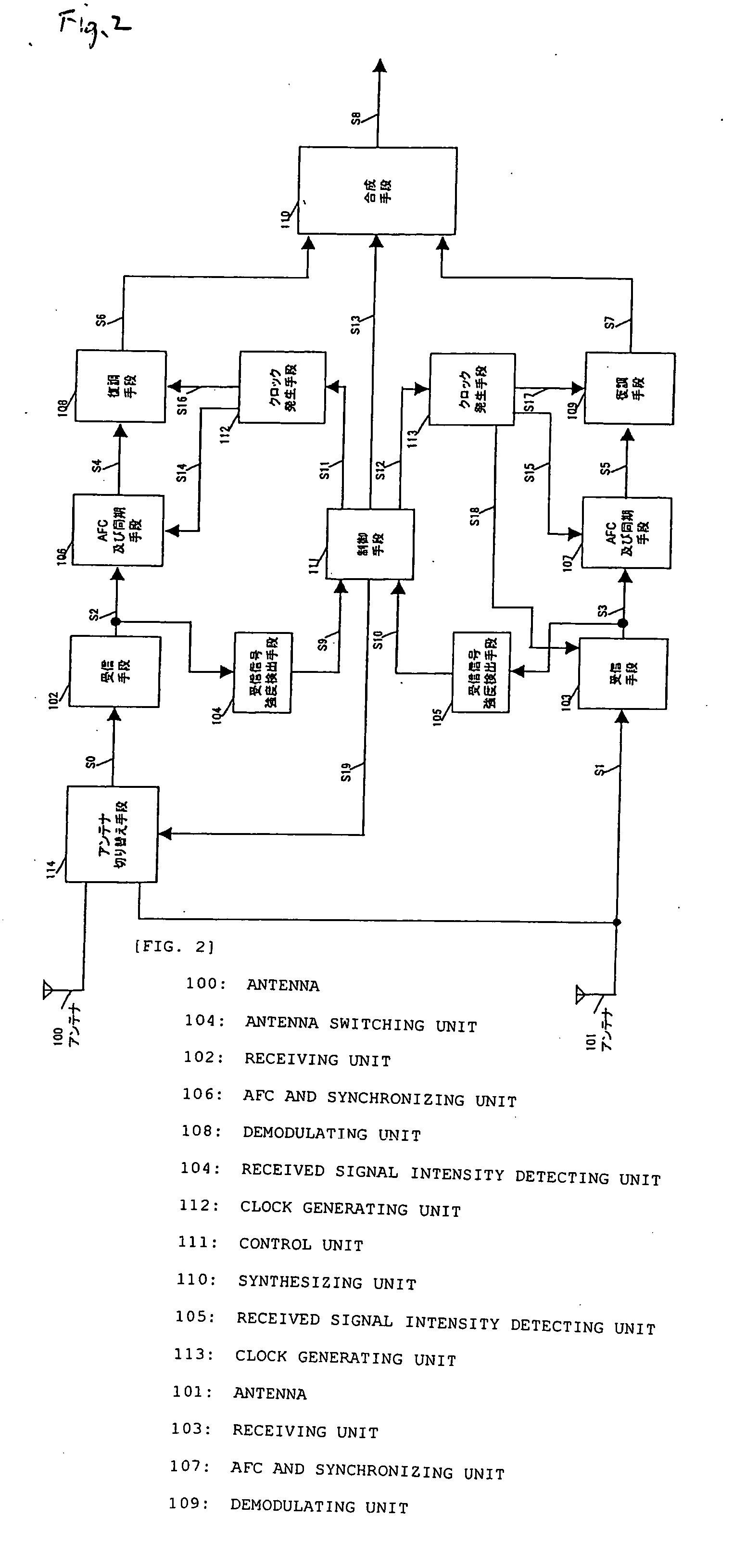
[0054]FIG. 2 is a block diagram showing the configuration of a diversity receiving device according to a second embodiment of the invention. In FIG. 2, an antenna switching unit 114 is added to the configuration of the first embodiment shown in FIG. 1. Hereinafter, a difference from the first embodiment will be described.

[0055] The antenna switching unit 114 selects one of signals coming into two of the antennas 100 and 101 on the basis of an antenna selection signal S19, and outputs the signal as a received signal S0 to the receiving unit 102. A diversity method using such an antenna switching unit is referred to as an antenna selection synthesis diversity.

[0056] The control unit 111 receives the reception intensity detection signals S9 and S10 and outputs clock interruption control signals S11 and S12 according to the reception intensity detection signals S9 and S10. Further, the control unit 111 outputs a synthesis pattern selection signal S13 for selecting a synthesis pattern ...

third embodiment

[0069]FIG. 3 is a block diagram showing the configuration of a diversity receiving device according to a third embodiment of the invention. In FIG. 3, reference numeral 100 denotes a first antenna, reference numeral 101 denotes a second antenna, reference numeral 102 denotes a receiving unit of a first system, reference numeral 103 denotes a receiving unit of a second system, reference numeral 104 denotes a received signal intensity detecting unit of the first system, reference numerals 105 denotes a received signal intensity detecting unit of the second system, reference numeral 115 denotes an AFC and synchronizing unit which performs time-division processing, reference numeral 116 denotes a demodulating unit which performs time-division processing, reference numeral110 denotes a synthesizing unit, reference numeral 111 denotes a control unit, and reference numeral 117 denotes a clock generating unit. Here, two systems are exemplified as a plurality of systems.

[0070] The time-divi...


PUM


Abstract

A diversity receiving device includes a processing circuit in which receiving units, AFC and synchronizing units, and demodulating units for a plurality of systems are connected, received signal intensity detecting units 104 and 105 that detect the intensities of output signals of the respective receiving units so as to output reception intensity detection signals, a control unit that determines to select one system as a synthesis pattern of demodulation signals based on a predetermined judgment criterion according to the respective reception intensity detection signals or to select a plurality of systems so as to add demodulation signals and outputs a plurality of clock interruption control signals requesting the interruption of a clock supply to unselected systems and synthesis pattern selection signals designating a synthesis pattern of demodulation signals of the selected system, a plurality of clock supply units that interrupt the clock supply to the AFC and synchronizing units and the demodulating units of the unselected systems according to the clock interruption control signal, and a synthesizing unit that synthesizes demodulation signals of the selected system according to the synthesis pattern selection signals.

Description

BACKGROUND OF THE INVENTION [0001] 1. Field of the Invention [0002] The present invention relates to a diversity receiving device that selects at least one received signal from a plurality of systems. [0003] 2. Description of the Related Art [0004] In the mobile communication, a diversity receiving method that synthesizes received signals of a plurality of antennas or demodulation signals of a plurality of systems is adopted in order to improve the degradation of received signals due to multipath fading. In particular, in a diversity receiving method that synthesizes demodulation signals of a plurality of independent systems, enhancement of reception sensitivity is achieved to the maximum. [0005]FIG. 14 is a block diagram showing the configuration of a known diversity receiving device. Here, two systems are exemplified as a plurality of systems. In FIG. 14, signals S100 and S101 received by antennas 200 and 201 are input to receivers 202 and 203, respectively, such that baseband rec...

Claims


Application Information

Patent Timeline
IPC IPC(8): H04L1/02
CPCH04B7/082H04B7/0877H04W52/028Y02D30/70
Inventor KAWADA, TOMOHARUNAGAO, AKIFUMINAGASAWA, YUKIYOSHI
Owner SOCIONEXT INC
Why Eureka
Try Eureka