Steam generating device

Inactive Publication Date: 2007-08-16
CHIANG LI YUAN
View PDF12 Cites 8 Cited by
  • Summary
  • Abstract
  • Description
  • Claims
  • Application Information

AI Technical Summary

Benefits of technology

[0005] The steam travels the lower space and is heated to become steam which then enters into the upper space and enters into the chamber. The travel distance of the water is long enough so that the water is heated for longer time. The steam is still heated in

Problems solved by technology

Besides, the steam generating device includes a cylindrical body which occupies too much space.
In addition, the path that the water and steam travels is short and the distance that the blast hole and the communication path be

Method used


Image

  • Steam generating device
  • Steam generating device
  • Steam generating device

Examples


Example

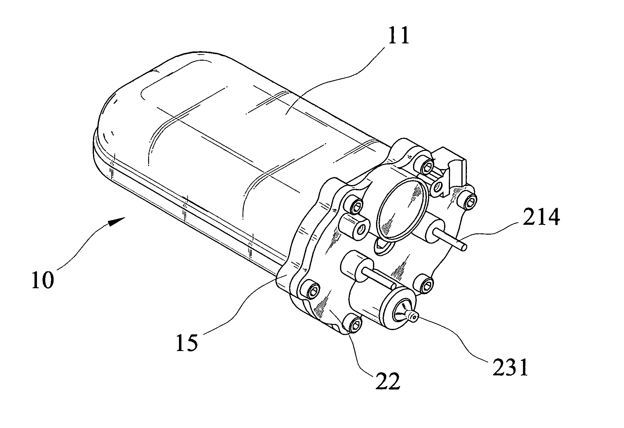
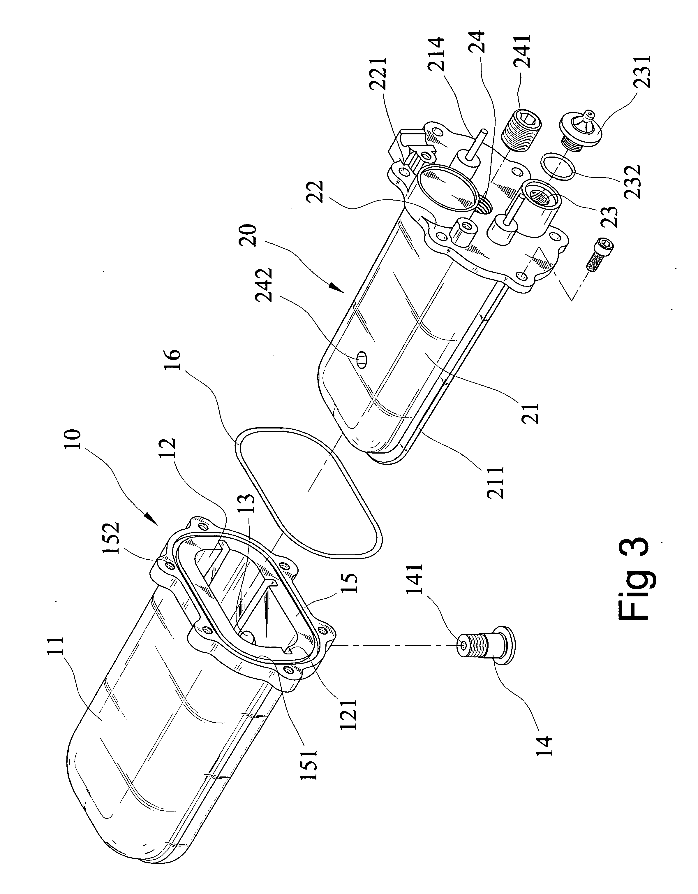
[0016] Referring to FIGS. 1 to 6, the steam generating device of the present invention comprises a flat casing 10 including a first body 11 which has a flat O-shaped cross section and includes a close end and an open end. A hollow interior 12 is defined in the casing 10 and two grooves 121 are defined in an inner periphery of the hollow interior 12. An end connection plate 15 extends perpendicularly outward from the open end of the casing 10 and includes a plurality of threaded connection holes 152. A seal 16 is engaged with a receiving groove 151 defined in the end connection plate 15. A hole 13 is defined through an underside of the first body 11.

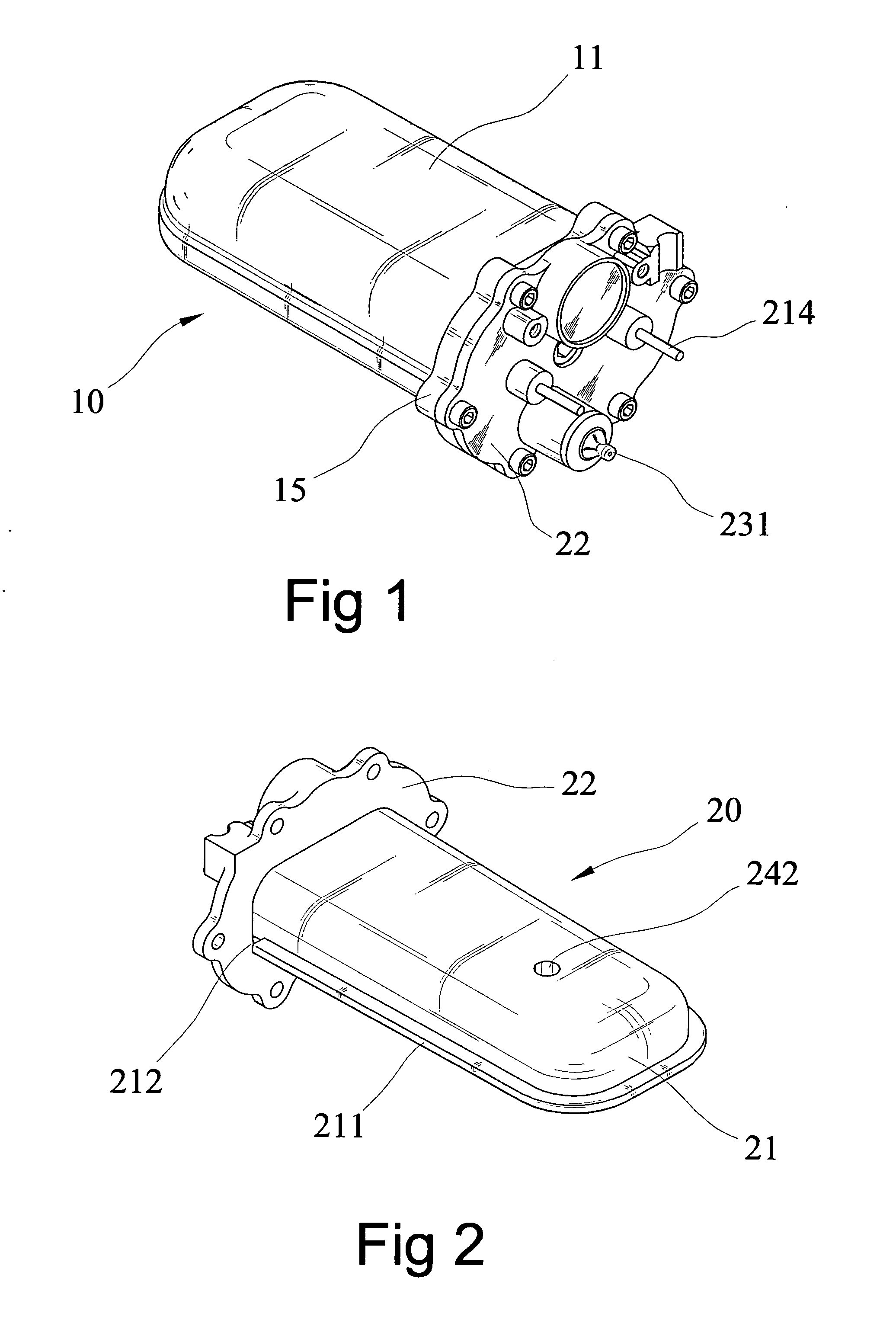
[0017] A heating device 20 has a second body 21 which is sized and shaped to be received in the interior 12 of the casing 10. Two flanges 211 extend from an outside of the second body 21 and are engaged with the two grooves 121. The second body 21 has an end board 22 which has a plurality of through holes 221. Bolts extend through the th...


PUM


Abstract

A steam generating device includes a flat casing and a heating device is received in the casing. The heating device includes flanges which are engaged with grooves in the casing so as to define a lower space and an upper space between the heating device and the inner periphery of the casing. A seal is clamped between the heating device and casing to prevent foreign objects entering the casing. The heating device includes a chamber which is in communication with a hole defined in the bottom of the casing. Water is introduced into the lower space and steamized by the heating device, the steam enters into the upper space via passages and enters into the camber and blasts out from the hole of the casing. The steam travels a long path in the casing and is heated sufficiently so as to increase the efficiency for generating the steam.

Description

FIELD OF THE INVENTION [0001] The present invention relates to a steam generating device for efficiently generating steam. BACKGROUND OF THE INVENTION [0002] A conventional steam generating device is disclosed in U.S. Pat. No. 6,748,904, and which includes a metal casing with a plurality of cambers defined therein and a heating member is received in the casing. The chambers are in communication with each other so that water in the casing can be heated in each chamber in sequence, and then enter into a steam room. The heating member is made by metal and is connected to the casing. No proper sealing device is provided between the casing the heating member so that water might enters into the steam room and the temperature of the steam is therefore reduced. Part of the steam is cooled into liquid water so that the steam blast out from the steam generating device includes liquid water particles. Besides, the steam generating device includes a cylindrical body which occupies too much spac...

Claims


Application Information

Patent Timeline
IPC IPC(8): F27D11/00
CPCF22B1/284
Inventor CHIANG, LI-YUAN
Owner CHIANG LI YUAN
Why Eureka
Try Eureka