Card Connector

Inactive Publication Date: 2011-06-23
CHENG UEI PRECISION IND CO LTD
View PDF4 Cites 6 Cited by
  • Summary
  • Abstract
  • Description
  • Claims
  • Application Information

AI Technical Summary

Benefits of technology

[0006]As described above, if the free ends of the first and second hook portions being extended into the observation slot can be observed to check the inserting direction of the cam lever, which wil

Problems solved by technology

Nevertheless, since the first hook portion and the second hook portion have a small difference in length, the cam lever is easily to be assembled in a reverse direction, that is, the second hook portion is inserted into the receiving hole and the

Method used


Image

  • Card Connector
  • Card Connector
  • Card Connector

Examples


Example

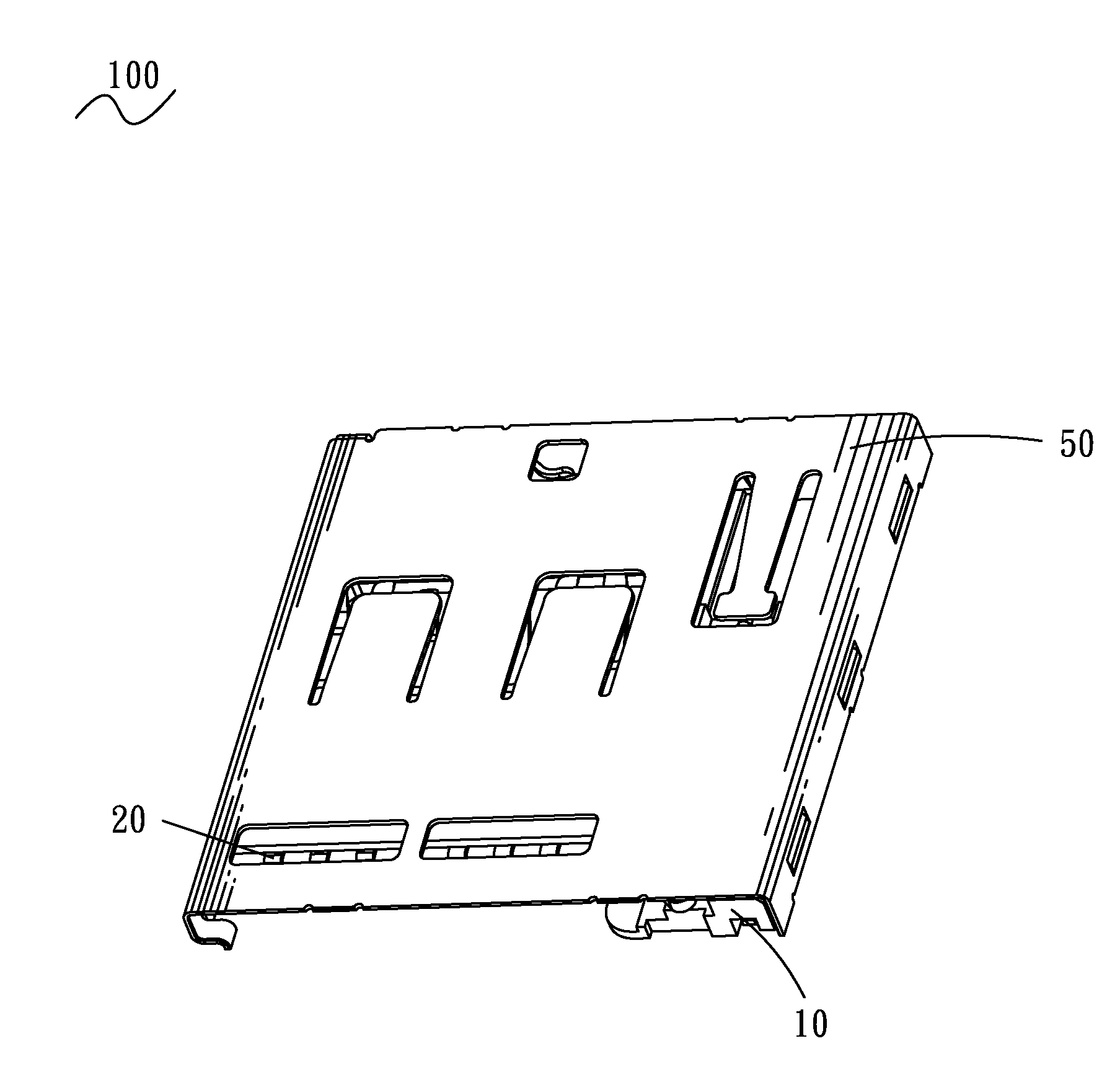
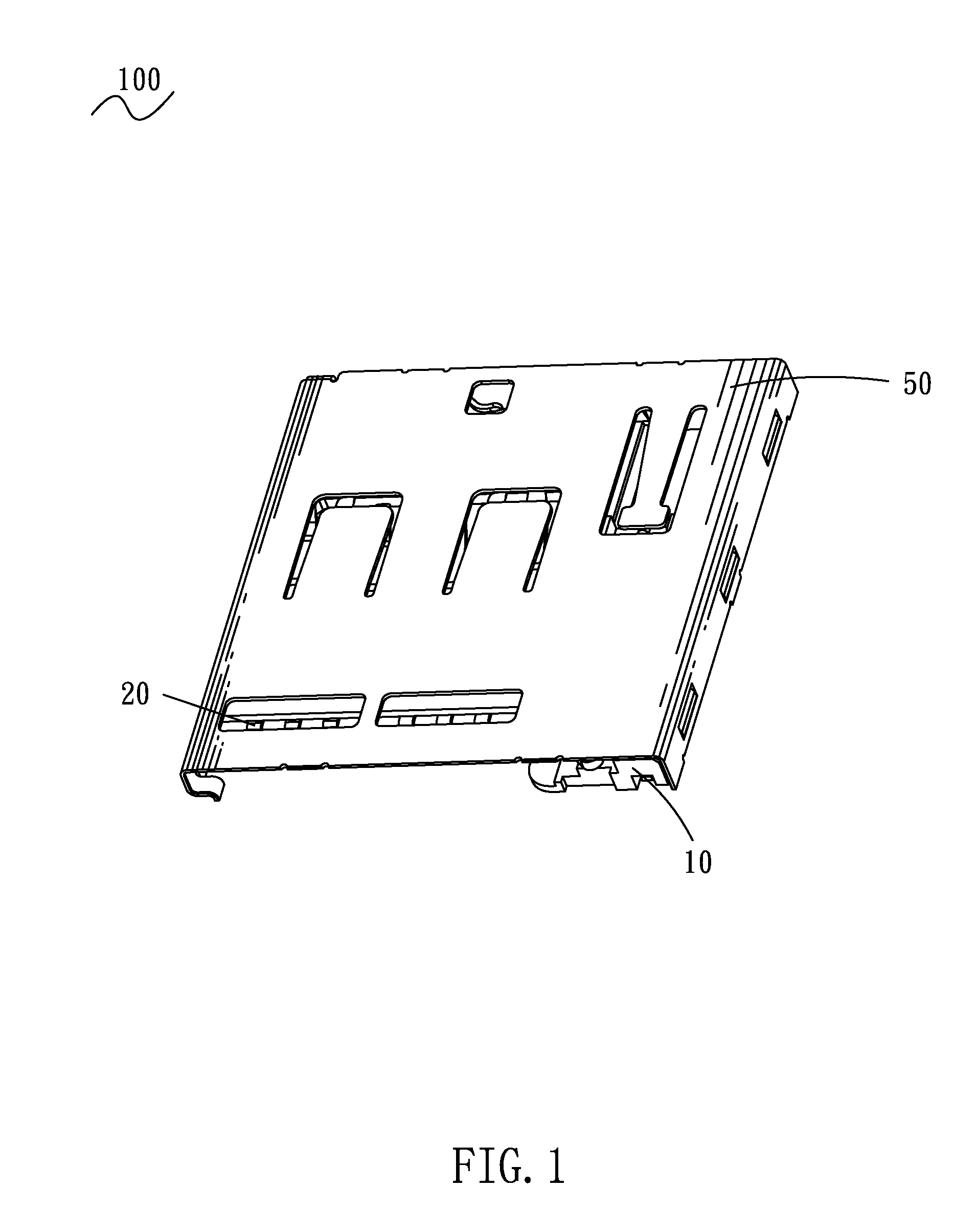
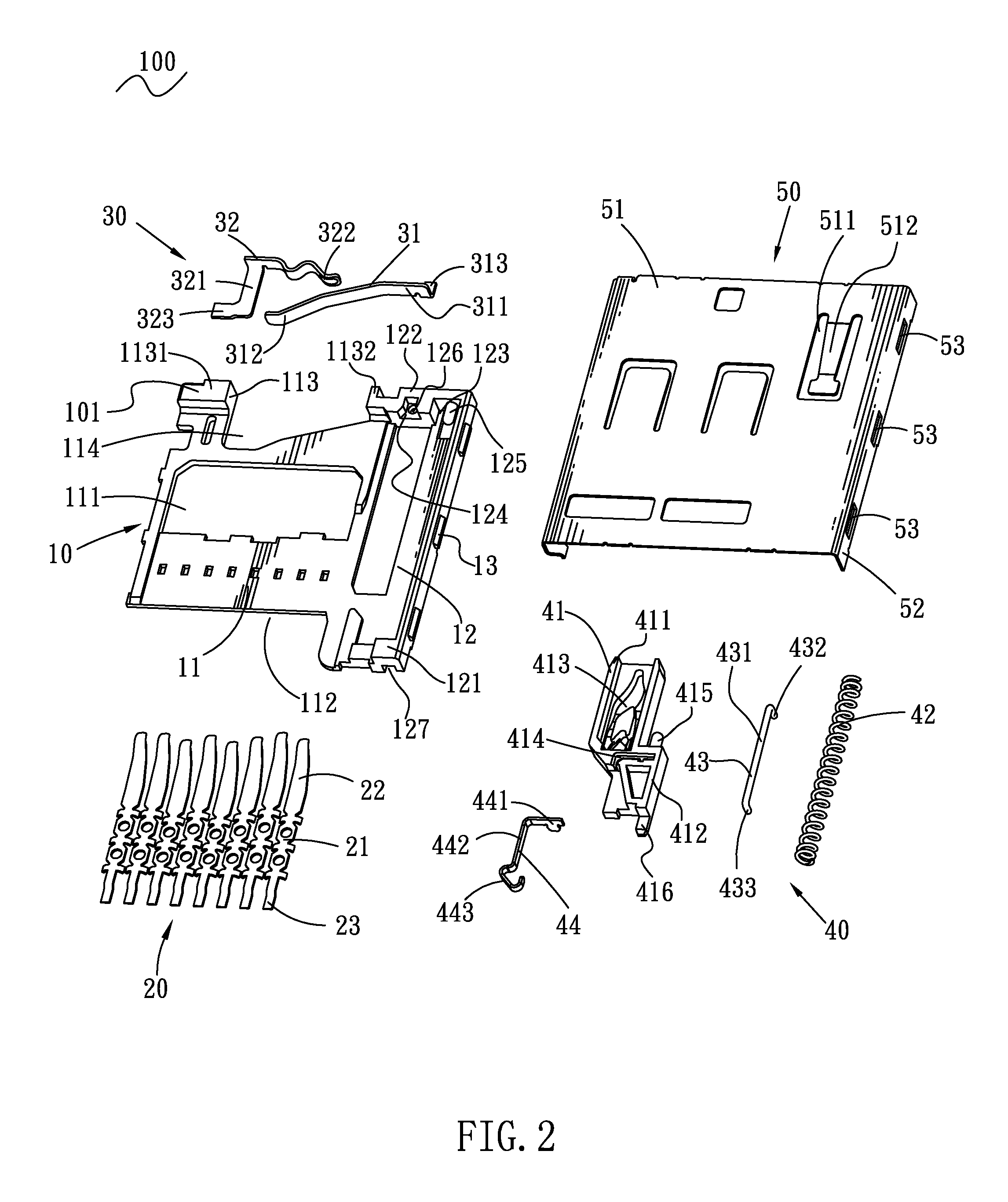
[0014]Referring to FIG. 1 and FIG. 2, a card connector 100 in accordance with the present invention is shown. The card connector 100 includes a substantial rectangular insulating housing 10, a plurality of conductive terminals 20, a monitoring assembly 30 and an ejection mechanism 40 held in the insulating housing 10 respectively, and a shield 50 coupled with the insulating housing 10. Herein, supposing a card 60 (shown in FIG. 4) is inserted into the card connector 100 along a front and rear inserting direction, for clear description.

[0015]Referring to FIG. 2 and FIG. 3, the insulating housing 10 defines a top 101, a bottom 102 opposite to the top 101 and a rear surface 103 contiguous to the top 101 and the bottom 102. The top 101 has a receiving space 11 reaching a front end of the insulating housing 10 for receiving the card 60 therein and a sliding groove 12 locating alongside of the receiving space 11 and communicating with the receiving space 11. A bottom of the receiving spac...


PUM


Abstract

A card connector has an insulating housing defining a top, a bottom opposite to the top. An ejection mechanism is disposed at one side of the insulating housing. The ejection mechanism includes a slider, an elastic element and a cam lever. Two opposite ends of the cam lever respectively have a first hook portion for being fixed in a receiving hole defined at the top of the insulating housing and a second hook portion for being movably arranged in the slider and different in length with the first hook portion. The bottom of the insulating housing defines an observation slot communicating with the receiving hole at a portion corresponding to the receiving hole. The height of the receiving hole is shorter than the length of one of the first and second hook portions and not shorter than the other of the first and second hook portions.

Description

BACKGROUND OF THE INVENTION[0001]1. Field of the Invention[0002]The present invention relates to a card connector, and more particularly to a card connector with an ejection mechanism.[0003]2. The Related Art[0004]A conventional card connector has an insulating housing, a shield, a plurality of conductive terminals and an ejection mechanism mounted in the insulating housing. The insulating housing has a receiving space for receiving an inserted card, and a sliding groove disposed at a side of the receiving space and communicating with the receiving space capable of receiving the ejection mechanism. The ejection mechanism has a slider and a cam lever. The slider defines a trace trough therein. The cam lever have two opposite ends respectively bent towards a same side to form a first hook portion and a second hook portion shorter than the first hook portion in length. The first hook portion is pivotally received in a receiving hole of the insulating housing, and the second hook portio...

Claims


Application Information

Patent Timeline
IPC IPC(8): H01R13/62
CPCH01R13/633H01R12/7094
Inventor YANG, CHIH-LING
Owner CHENG UEI PRECISION IND CO LTD
Why Eureka
Try Eureka