Disk drive fastening mechanism

a technology of fastening mechanism and drive, which is applied in the direction of static indicating device, electric apparatus casing/cabinet/drawer, instruments, etc., can solve the problems of affecting production efficiency, affecting assembly time, and complicated production process, etc., to achieve the effect of simplifying operation and saving assembly tim

Active Publication Date: 2008-06-24
MITAC INT CORP
View PDF8 Cites 17 Cited by
  • Summary
  • Abstract
  • Description
  • Claims
  • Application Information

AI Technical Summary

Benefits of technology

[0009]In view of the aforesaid problems, the primary object of the invention is to provide a disk drive fastening mechanism to mount disk drives on a computer chassis without using tools such as screw drivers to save assembly time and simplify operation.

Problems solved by technology

Such a fastening method has disadvantages.
Production process is thus complicated and tedious.
To improve production efficiency is difficult.
But this still requires screw drivers for assembly and disassembly.

Method used


Image

  • Disk drive fastening mechanism
  • Disk drive fastening mechanism
  • Disk drive fastening mechanism

Examples


first embodiment

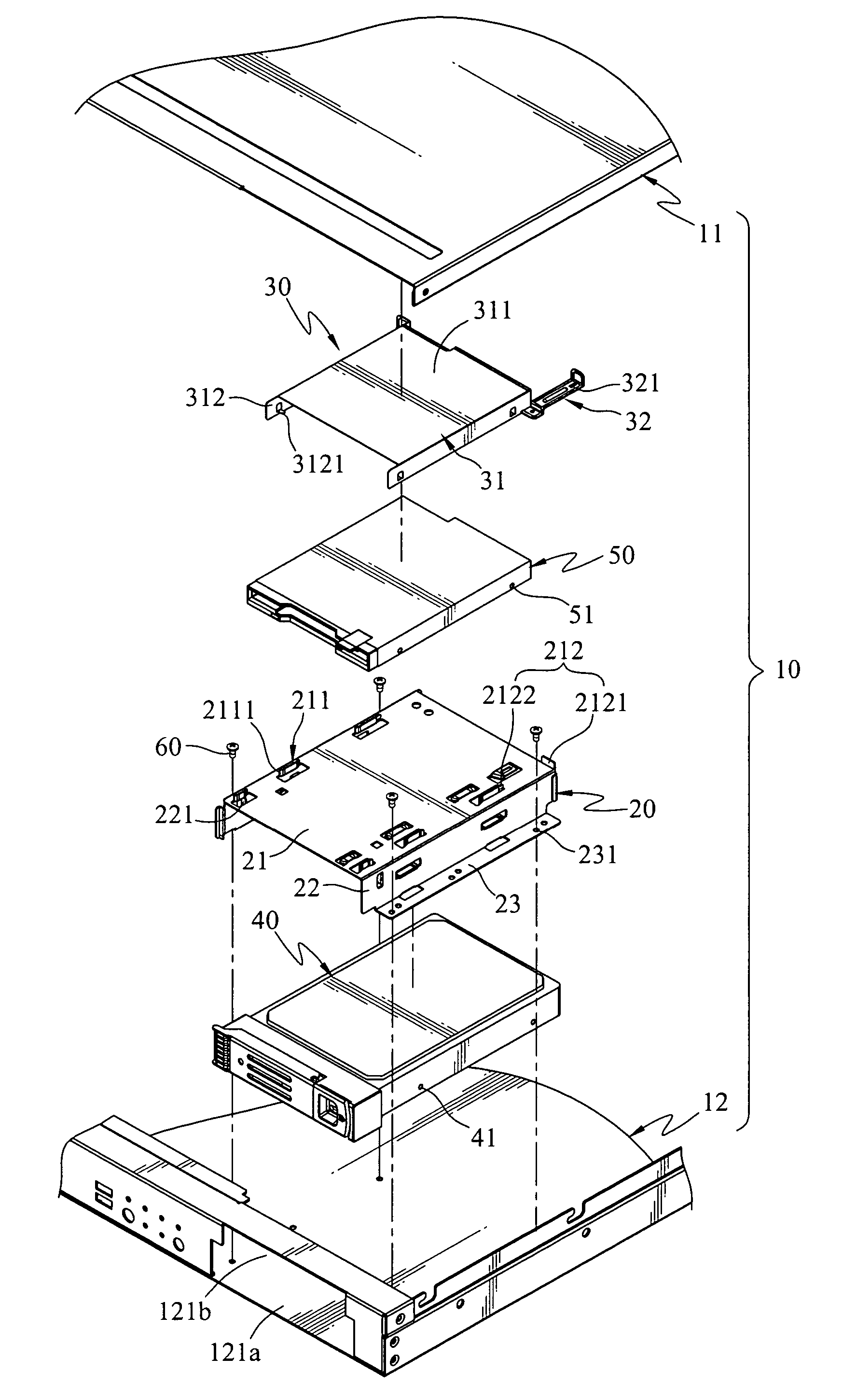
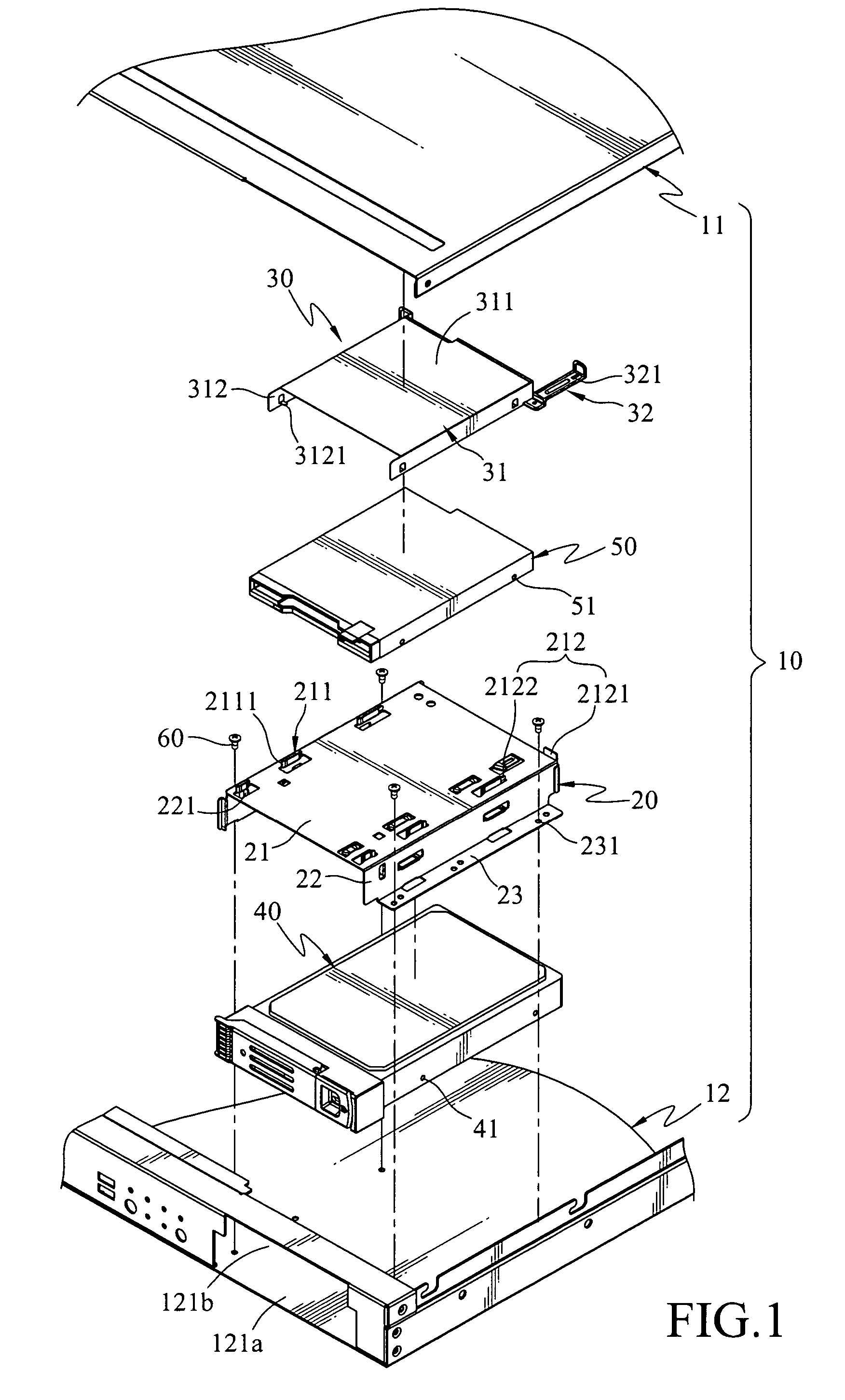
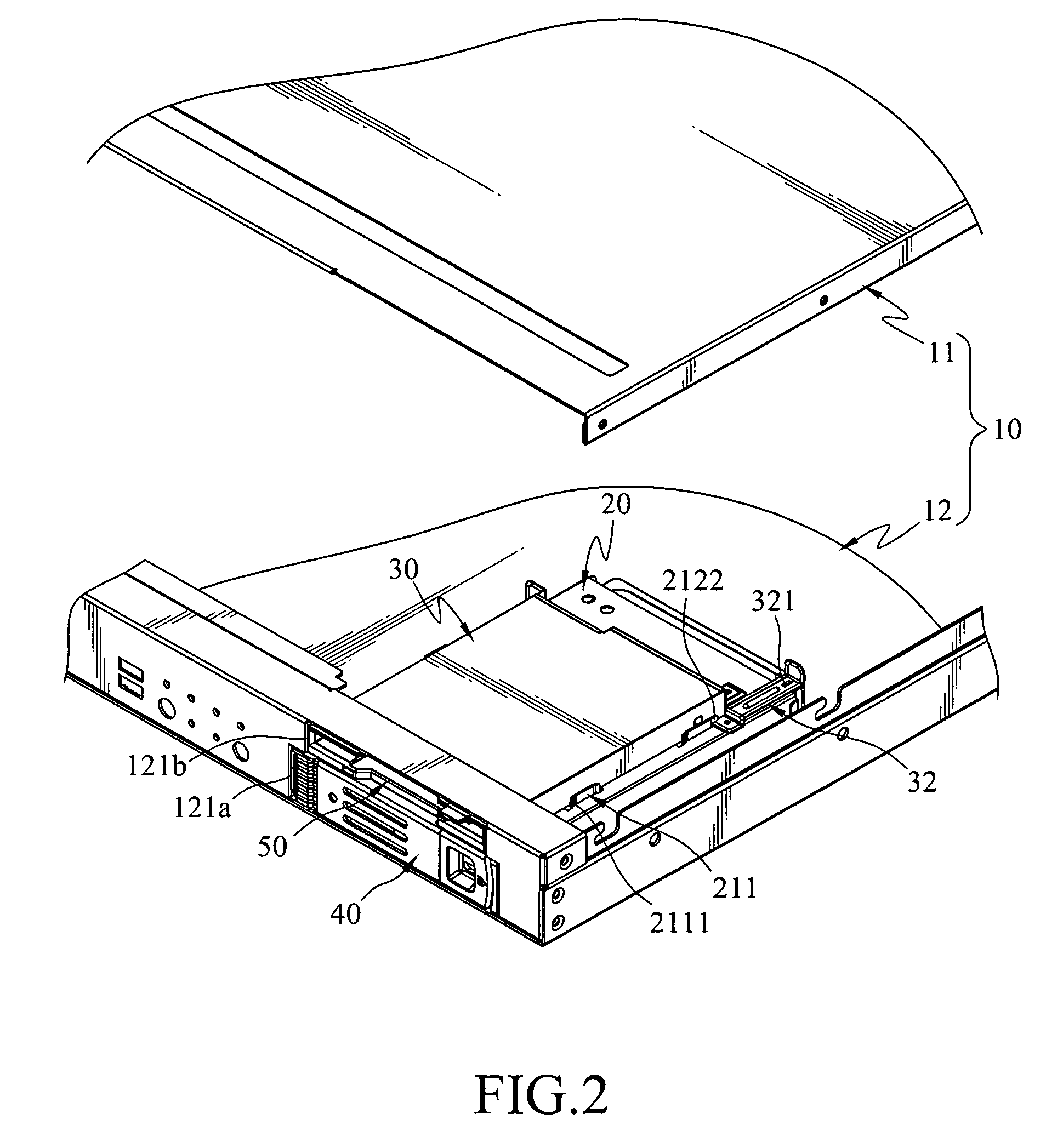
[0020]Refer to FIGS. 1, 2, 3, and 4 for the disk drive fastening mechanism of the invention. It includes a computer chassis 10, a first disk drive rack 20 and a second disk drive rack 30.

[0021]The computer chassis 10 includes a top cover 11 and a base 12 that are connectable to each other. The base 12 has a first frame opening 121a and a second frame opening 121b.

[0022]The first disk drive rack 20 is located on the base 12 for housing a first disk drive 40, and the first frame opening 121a of the base 12 is used for loading the first disk drive 40. The first disk dive rack 20 includes a first top plate 21, two first side plates 22 and two fastening plates 23. The two first side plates 22 face to each other and respectively have one end connected to the first top plate 21 and the other end connected the fastening plates 23. The fastening plates 23 are fastened to the base 12.

[0023]The first top plate 21 has a first retaining set 211 and a second retaining set 212. The first retainin...

second embodiment

[0030]Thus, according to the invention, the second disk drive 50 can be mounted onto the computer chassis 10 without using tools such as screw drivers. Assembly time may be reduced and operation is simpler.

[0031]The first disk drive rack 20 in the first embodiment set forth above may be dispensed with. The elements except for the first disk drive rack 20 may be directly formed on the base 12 of the computer chassis 10. The elevation difference of the top cover 11 and the base 12 is the height of the second disk drive rack 30 to be held. Refer to FIG. 6 for the exploded view of a second embodiment of the invention.

[0032]For fastening a disk drive 80 in a disk drive rack 70, couple wedge members 7121 on sides plates 712 of a bracket 71 with apertures 81 formed on the disk drive 80; slide the disk drive rack 70 and the disk drive 80 between the gap of first retaining members 1221 of a first retaining set 122; load the disk drive 80 through a frame opening 121 until one end of an elasti...


PUM


Abstract

A disk drive fastening mechanism includes a computer chassis, a first disk drive rack and a second disk drive rack. The computer chassis has a top cover and a base that are connectable to each other. The first disk drive rack including a first retaining set and second retaining set is located on the base for housing a first disk drive. The second disk drive rack is movably mounted onto the top surface of the first disk drive rack for housing a second disk drive, confined in the first dimension and second dimension by the first retaining set and the second retaining set, and confined in the third dimension by the top cover and the first disk drive rack. Hence the second disk drive can be installed on the computer chassis without using tools so as to save installation time and simplify operation.

Description

CROSS-REFERENCE TO RELATED APPLICATIONS[0001]This non-provisional application claims priority under 35 U.S.C. § 119(a) on Patent Application No(s). 94102951 filed in Taiwan, R.O.C. on Dec. 31, 2005, the entire contents of which are hereby incorporated by reference.FIELD OF THE INVENTION.[0002]The invention relates to a fastening mechanism for fastening a disk drive on a computer chassis, and particularly to a fastening mechanism that may be operated without using tools.BACKGROUND OF THE INVENTION[0003]The hardware of a computer system generally includes a host motherboard, various interface cards and magnetic disk drives (such as floppy disk drives, hard disk drives, optical disk drives and the like). This equipment is housed in a chassis, or a computer chassis. The computer chassis includes a case that has a housing space and a cover to seal the housing space. As the magnetic disk drives can be configured selectively, to facilitate installation and expansion, the computer chassis u...

Claims


Application Information

Patent Timeline
Patent Type & Authority Patents(United States)
IPC IPC(8): G06F1/16
CPCG06F1/184G06F1/187
Inventor TSAI, CHENG-YU
Owner MITAC INT CORP
Why Eureka
Try Eureka