

Multi-Band Compact Pifa Antenna With Meandered Slot (s)
- Summary
- Abstract
- Description
- Claims
- Application Information
AI Technical Summary
Benefits of technology
Problems solved by technology
Method used
Image

Examples
Embodiment Construction
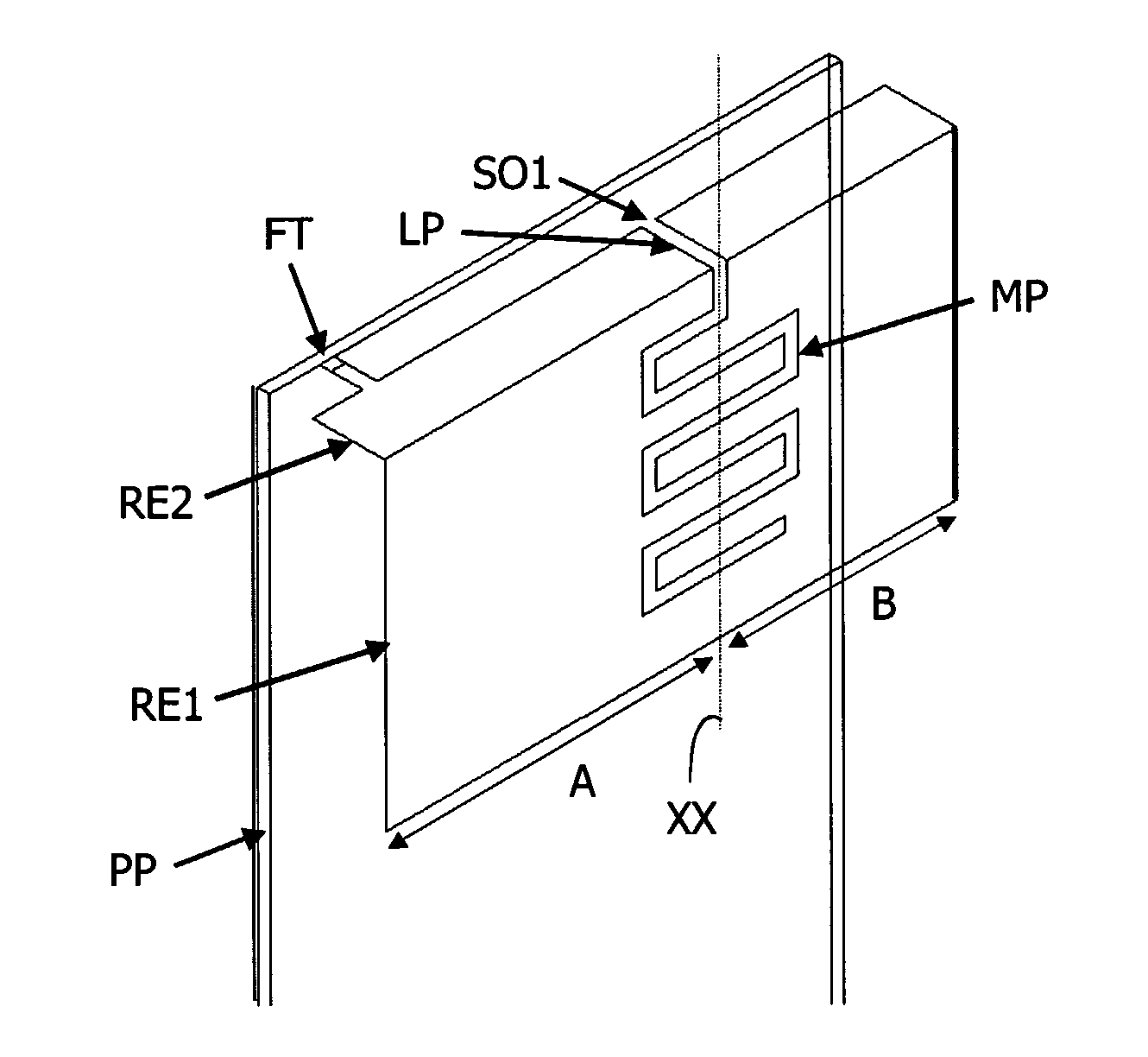
[0040] The invention proposes to mount a compact PIFA antenna assembly having at least one meandered slot in the space within a mobile phone normally previously occupied by a larger antenna. A first example of embodiment of such a PIFA antenna is illustrated in FIG. 4.
[0041] The compact antenna assembly, according to the invention, comprises a PIFA antenna mounted on a printed circuit board (PCB) PP. The PIFA antenna comprises a radiating element RE1, RE2, a feed tab (or pin) FT and a (dual-banding) main slot SO1 defined in the radiating element RE1, RE2.
[0042] The radiating element comprises first RE1 and second RE2 parts approximately perpendicular one to the other and having preferably approximately a rectangular shape. The first part RE1 is located in a first plan facing and parallel to a ground plane mounted on a face of the printed circuit board (PCB) PP. The second part (or top plate) RE2 is located in a second plane perpendicular to the ground plane.
[0043] The feed tab FT...
PUM
 Abstract
Description
Claims
Application Information