Sleeve joint type hinge

a technology of sleeve joint and hinge, which is applied in the field of hinges, can solve the problems of inability to maintain the design of sleeve joint hinges in use, and achieve the effect of improving the durability of the design

Inactive Publication Date: 2007-09-20
JARLLYTEC CO LTD
View PDF12 Cites 37 Cited by
  • Summary
  • Abstract
  • Description
  • Claims
  • Application Information

AI Technical Summary

Benefits of technology

[0006]The present invention has been accomplished under the circumstances in view. According to one aspect of the present invention, the sleeve joint type hinge comprises a barrel, a pivot shaft, and at least one resilient friction member. The barrel has a first end, a second end opposite to the second end, and a receiving open chamber axially extending from the first end toward said second end and surrounded by an inside wall of the barrel. The pivot shaft is inserted into the receiving open chamber of the barrel and rotatable relative to the barrel, having a shaft body, two longitudinal locating grooves on the periphery of the shaft body at two opposite sides, a

Problems solved by technology

However, this design of sleeve joint type hinge is not durabl

Method used


Image

  • Sleeve joint type hinge
  • Sleeve joint type hinge
  • Sleeve joint type hinge

Examples


Embodiment Construction

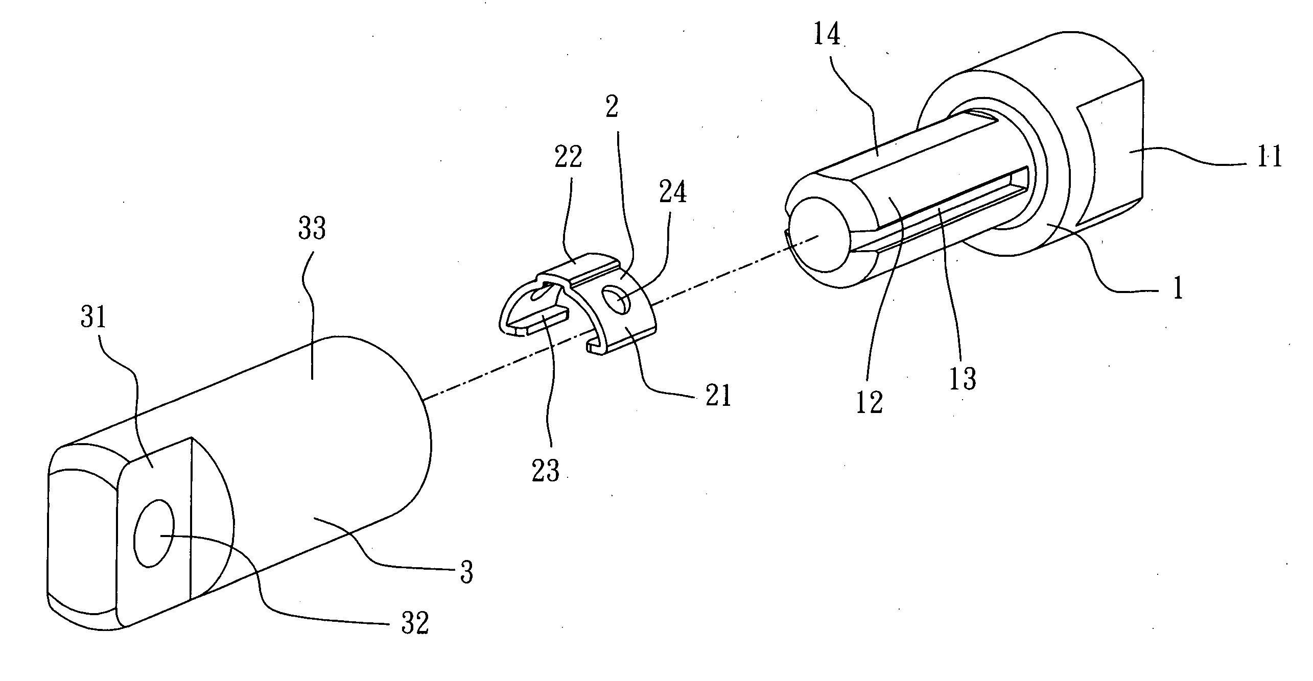
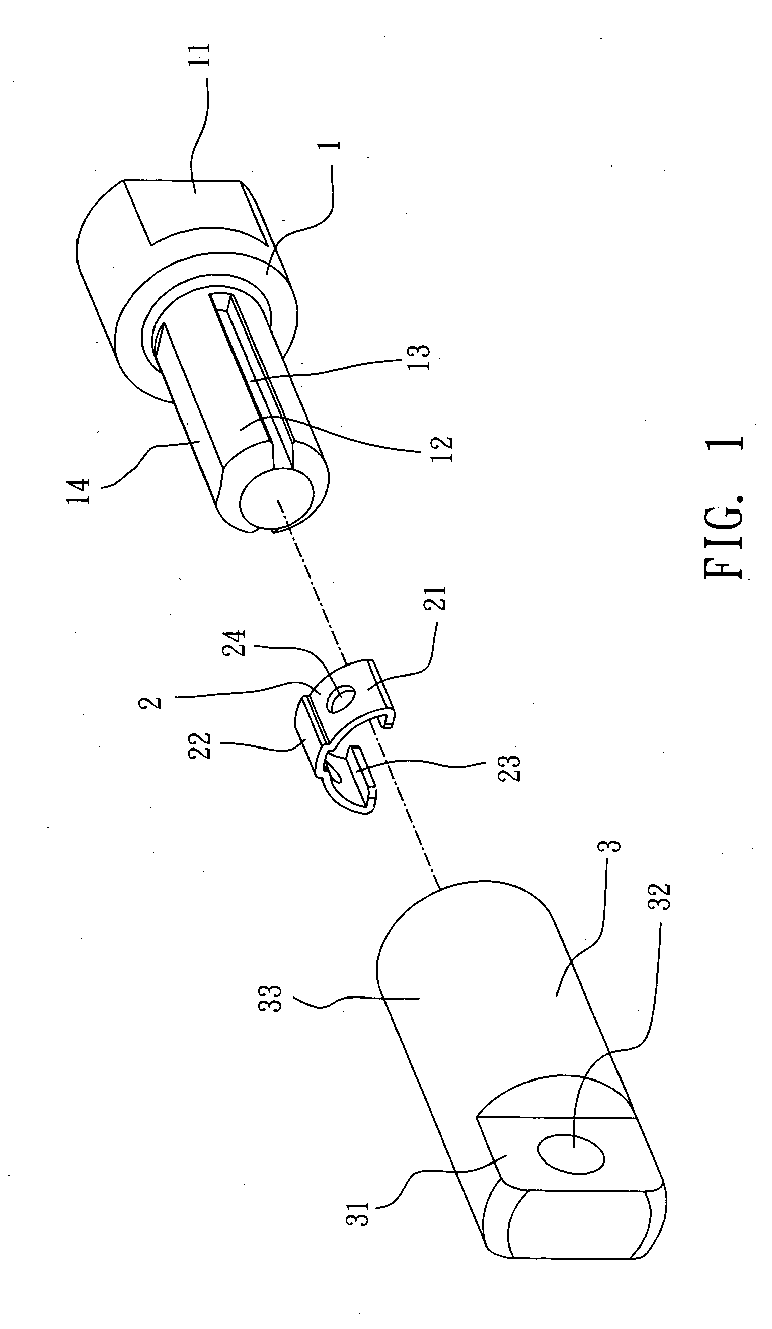
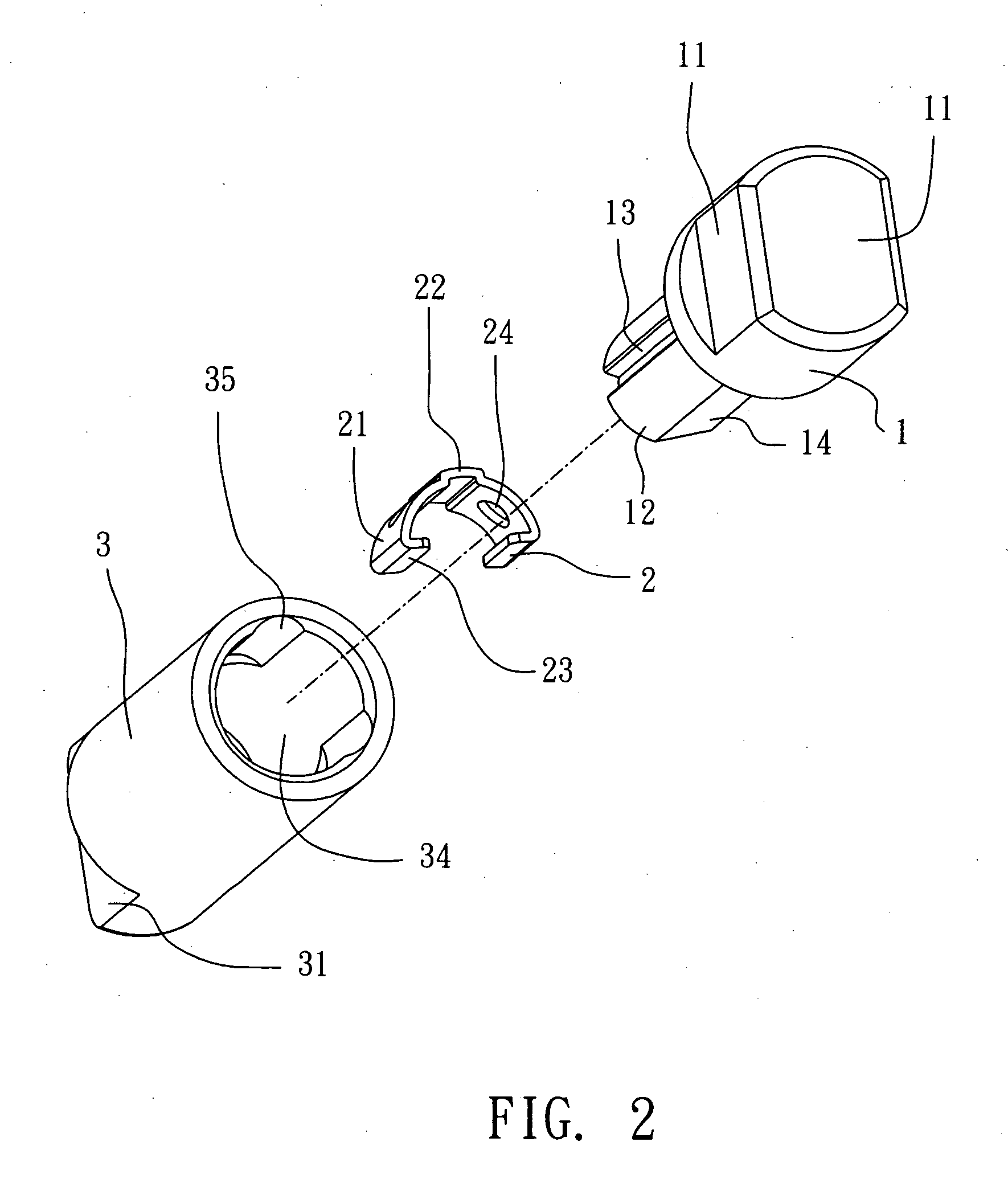
[0019]Referring to FIGS. 1˜3, a sleeve joint type hinge in accordance with a first embodiment of the present invention is shown comprised of a pivot shaft 1, a friction member 2, and a barrel 3.

[0020]The pivot shaft 1 has a mounting portion 11 disposed at one side for fastening to a body, for example, the cover member of a mobile electronic device, and a shaft body 12 disposed at the other side for coupling to the barrel 3. The mounting portion 11 can be a triangular, rectangular, or polygonal prism. Further, the mounting portion 11 can be made having at least one, for example, a number of mounting through holes for fastening to the cover member of a mobile electronic device with fastening members, for example, screws. The shaft body 12 has two longitudinal locating grooves 13 on the periphery at two opposite sides, and at least one, for example, two tangential planes 14 longitudinally formed on the periphery and respectively equally spaced from the longitudinal locating grooves 13 ...


PUM


Abstract

A sleeve joint type hinge includes a barrel, a pivot shaft, inserted into and rotatable relative to the barrel, and an arched resilient friction member, which has two hooked portions respectively extending from the two distal ends thereof and hooked on the periphery of the pivot shaft and a middle protruding portion kept spaced from a tangential peripheral plane of the pivot shaft and disposed in close contact with the inside wall of the barrel to produce a friction resistance and to hold the pivot shaft positively in positive after each rotary motion of the pivot shaft relative to the barrel by an external biasing force.

Description

BACKGROUND OF THE INVENTION[0001]1. Field of the Invention[0002]The present invention relates to hinges and more particularly, to a sleeve joint type hinge, which has at least one friction member provided between a first hinge member (the barrel) and a second hinge member (the pivot shaft) to produce a friction resistance and to hold the second hinge member positively in position relative to the first hinge member after each rotary motion by an external biasing force.[0003]2. Description of the Related Art[0004]A consumer electronic product with a lifting cover such as mobile computer, electronic dictionary, mobile video player, cell phone, etc., commonly uses a hinge to coupled the cover to the base member so that the cover can be opened from or closed on the base member. Therefore, the hinge also determines the quality level of the product.[0005]A good hinge allows positive positioning and does not cause noises during operation. There is known a sleeve joint type hinge, which comp...

Claims


Application Information

Patent Timeline
IPC IPC(8): E05D11/08
CPCE05D11/082E05D11/105E05Y2201/48Y10T16/54038G06F1/1616G06F1/1681E05Y2900/606
Inventor TU, CHUNG-HO
Owner JARLLYTEC CO LTD
Why Eureka
Try Eureka