Hand-held power tool with grounding

a power tool and hand-held technology, applied in the field of hand-held power tools, can solve the problem of relative weak air flow and achieve the effect of maximum cooling efficiency

Inactive Publication Date: 2007-09-27
HILTI AG
View PDF8 Cites 16 Cited by
  • Summary
  • Abstract
  • Description
  • Claims
  • Application Information

AI Technical Summary

Benefits of technology

[0013] If a protective ground wire is used, e.g., because of the corresponding requirement to the power tool in question in the country of use, the wire passage region can be open by a simple secondary treatment. This enables a short connection between the related metallic part and the ground conductor, on one hand, and a simple mounting and a reliable fixation of the protective ground wire. At that, the wire passage region is adapted to the cross-section of the protective wire in order to minimize a possible pressure or temperature imbalance and a resulting reduction in the cooling efficiency.
[0022] It is advantageous when the opening means includes a film hinge that pivotally supports a predetermined region. The film hinge can be elastically or plastically deformed. In each case, the wire passage region can be formed without use of any tool, which substantially simplifies mounting of the protective ground wire.

Problems solved by technology

The drawback of the known construction consists in that because of the open transition region between the suction and pressure zones, only a relatively weak air flow is produced.
In addition, the protective ground wire has a relatively high freedom of movement that can lead to damages during the operation.

Method used


Image

  • Hand-held power tool with grounding
  • Hand-held power tool with grounding
  • Hand-held power tool with grounding

Examples


Embodiment Construction

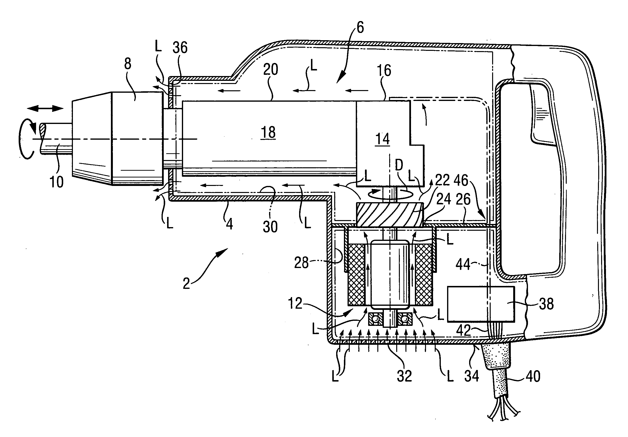
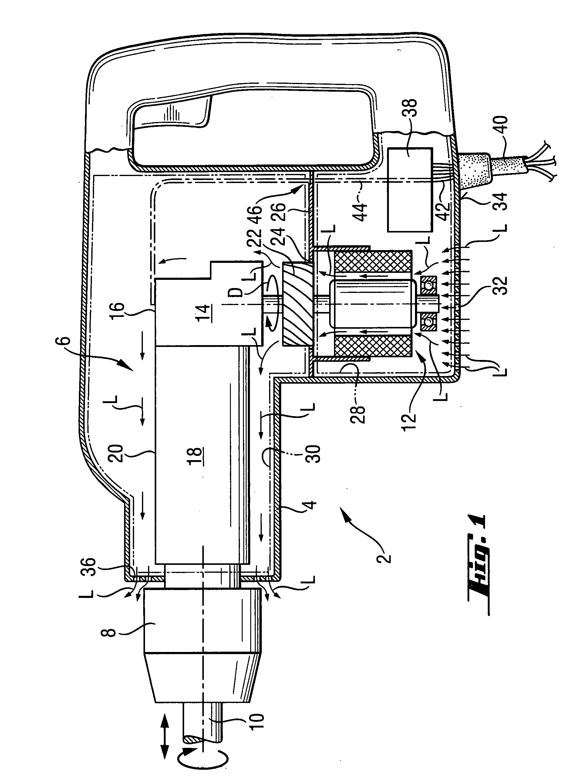
[0035] A hand-held power tool 2 according to the present invention, which is shown in FIG. 1, has a housing 4 in which there is arranged a drive 6 for driving a working tool 10 receivable in a chuck 8. The drive 6 includes a motor 12, a gear unit 14 located in a gear unit housing 16, and a percussion mechanism 18 arranged in a percussion mechanism housing 20. Alternatively, there can be provided a hand-held power tool 2 without the percussion mechanism 18.

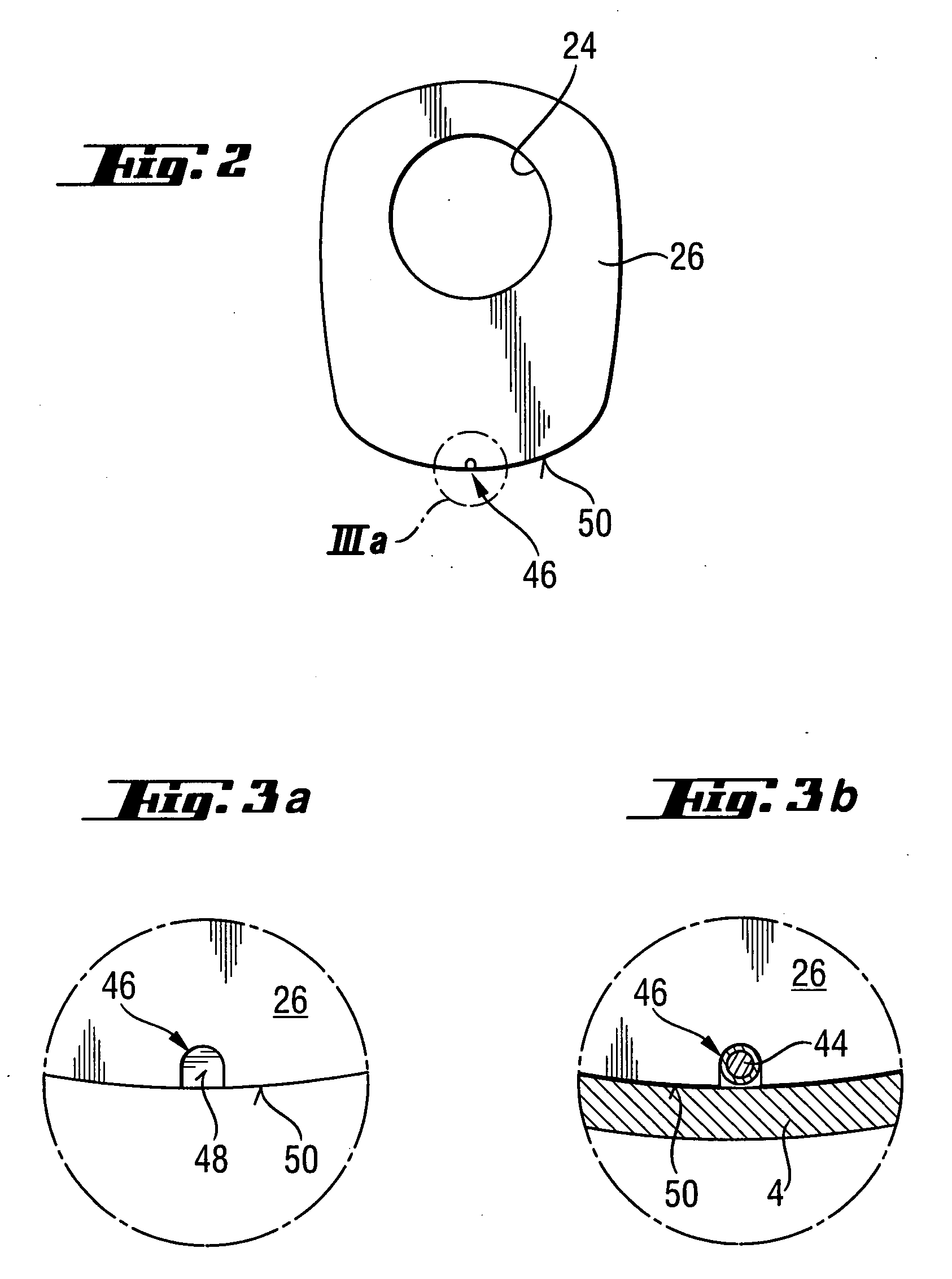
[0036] The motor 12 drives ventilation means 22 in form of a ventilator supported on a separation element 26, arranged on an opening 24 in the housing 4 and serving as air conducting means. The separation element 26 is form-or forcelockingly held on the housing 4, in a manner not shown in the drawing in detail, in the condition of the hand-held power tool 2 after the final assembly. Alternatively, the separation element can be formed as one-piece with a part of the housing 4. In each case, during rotation of the ventilation means ...


PUM

PropertyMeasurementUnit
pressureaaaaaaaaaa
cooling capacityaaaaaaaaaa
metallicaaaaaaaaaa

Abstract

An electrical hand-held power tool (2) includes a housing (4) in which a drive (6) is located, a ventilator (22) for forming a suction region (28) and a pressure region (30) in the housing (4) which provide for an air flow (L) that serves for cooling at least parts of the drive (6), and a separation element (26) arranged between the suction region (28) and the pressure region (30) and fixedly secured in the housing (4), the separation element (46) having an opening for forming a limited wire passage region (46) from the suction region (28) into the pressure region (30).

Description

BACKGROUND OF THE INVENTION [0001] 1. Field of the Invention [0002] The present invention relates to a hand-held power tool including a housing, a drive located in the housing and including a motor, a gear unit and, optionally, a percussion mechanism. The hand-held power tool further includes ventilation means for forming a suction region and a pressure region in the housing which provide for an air flow that serves for cooling at least parts of the drive, and a separation element arranged between the suction region and the pressure region and fixedly secured in the housing. [0003] 2. Description of the Prior Art [0004] In the hand-held power tools of the type described above, a constructive separation of the overpressure region in which ventilation means produces a blowing flow, and of the suction region in which the ventilation means produces a suction flow, insures a relatively high cooling capacity. [0005] German Publication DE 42 20 078 A1 discloses a hand-held power tool in wh...

Claims


Application Information

Patent Timeline
Patent Type & Authority Applications(United States)
IPC IPC(8): E21B19/16E21B17/22E21B19/18E21B3/00
CPCB25F5/008
Inventor BRITZ, RORYONTL, RAINERHOFBRUCKER, THOMAS
Owner HILTI AG
Why Eureka
Try Eureka