Connector connecting construction and a connector connecting method

Inactive Publication Date: 2005-09-27
SUMITOMO WIRING SYST LTD
View PDF6 Cites 11 Cited by
  • Summary
  • Abstract
  • Description
  • Claims
  • Application Information

AI Technical Summary

Benefits of technology

[0009]The movable protecting portion is retractable in the assembling process. Thus, the receptacle can be shorter as compared to a case where the receptacle is elongated to protect the connecting portion. Thus, a connection stroke of the connectors can be shorter and the connectors can be smaller.
[0010]The protecting-portion guiding means preferably comprises at least one guide pin on the movable protecting portion and at least one guide groove in the holder. The guide pin slides

Problems solved by technology

However, this disadvantageously leads to a larger conn

Method used


Image

  • Connector connecting construction and a connector connecting method
  • Connector connecting construction and a connector connecting method
  • Connector connecting construction and a connector connecting method

Examples


Example

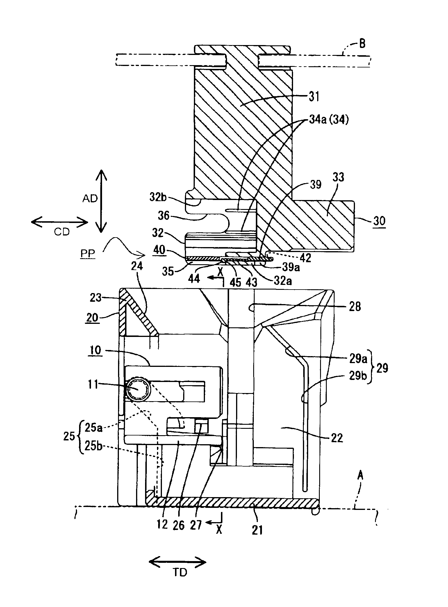
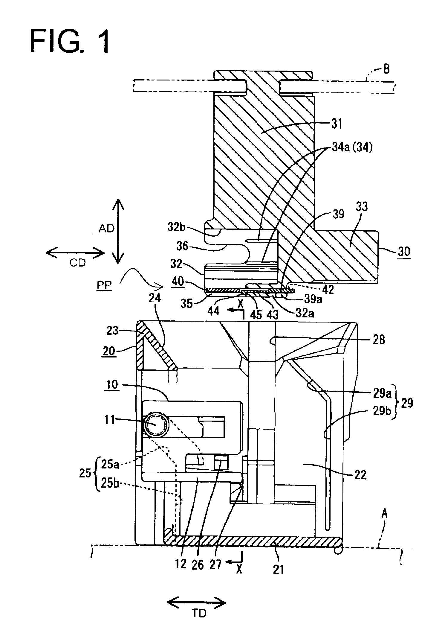
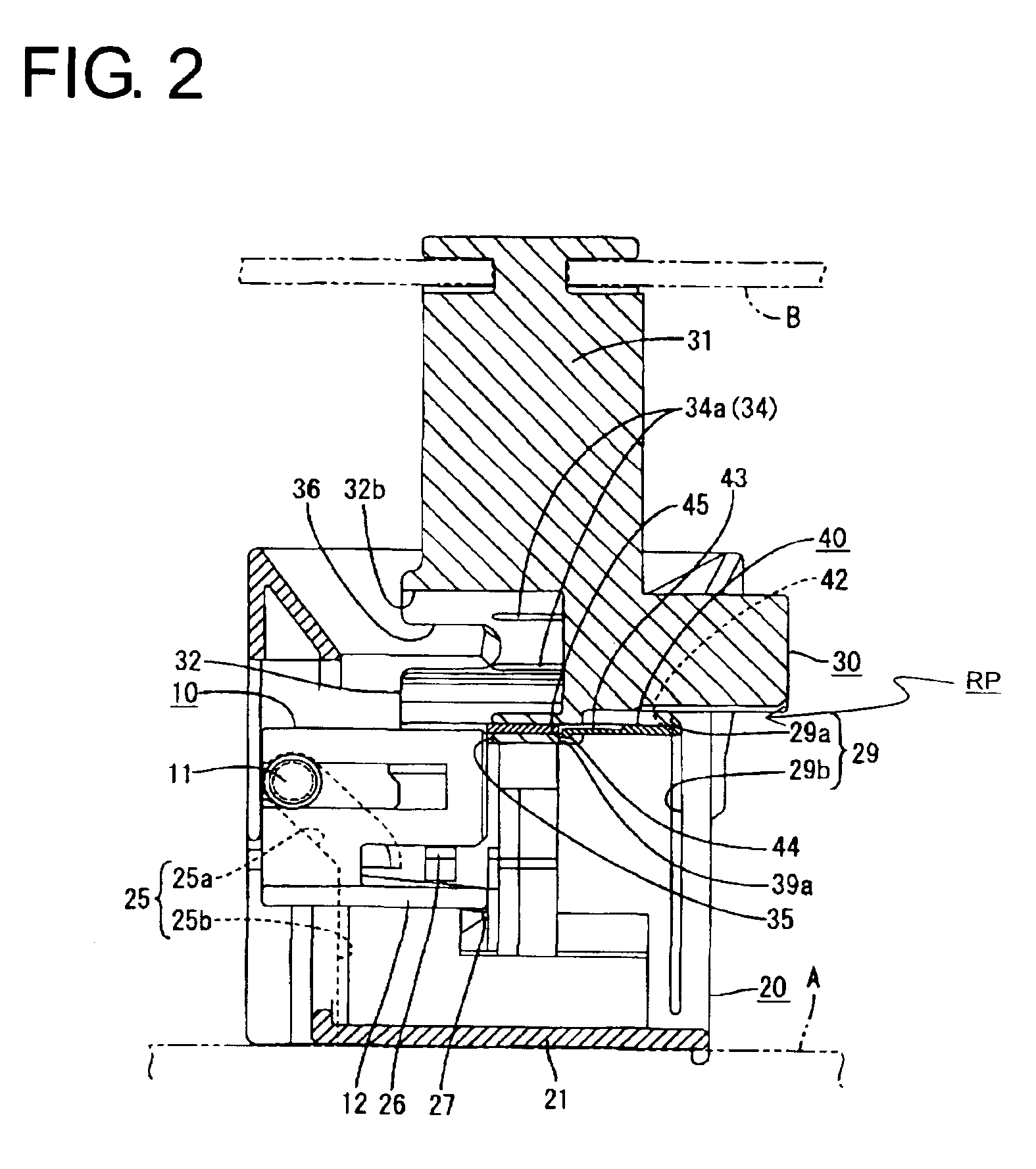
[0029]A preferred embodiment of the invention is described with reference to FIGS. 1 to 10. This embodiment illustrates a construction for assembling a meter module of an automotive vehicle. More particularly, a female connector 10 on a dashboard A of a vehicle body and a male connector 30 on an instrument panel B are connected as the dashboard A and the instrument panel B are assembled. In the following description, reference is made to FIG. 1 concerning vertical and transverse directions.

[0030]A holder 20 is fixed to a surface of the dashboard A facing the instrument panel B as shown in FIG. 1, and the female connector 10 is mounted laterally into the holder 20. As shown in FIGS. 1, 5 to 7, the female connector 10 is a wide block and female terminal fittings (not shown) connected with wires (not shown) are accommodated in the female connector 10. Substantially cylindrical guide pins 11 project sideways from left ends of each of the opposite outer side surfaces of the female connec...


PUM


Abstract

A female connector (10) is assembled with a holder (20) on a dashboard (A) and a male connector (30) is assembled with an instrument panel (B). The male connector (30) has a receptacle 32 with a cut-out (35) for receiving the female connector (10). Guide pins (11) of the female connector (10) slide along guide grooves (25) of the holder (20) to displace the female connector (10) normal to an assembling direction and to connect the female connector (10) with the male connector (30). A movable protecting portion (40) is displaced from a protecting position where the movable protecting portion (40) covers the cut-out (35) to a retracted position RP where the movable protecting portion (40) is retracted from the cut-out (35) by sliding movements of guide pins (42) of the movable protection portion (40) along guide grooves (29) of the holder (20).

Description

BACKGROUND OF THE INVENTION[0001]1. Field of the Invention[0002]The invention relates to a connector connecting construction and to a connector connecting method.[0003]2. Description of the Related Art[0004]U.S. Pat. No. 6,217,363 and FIG. 11 herein relate to a connector connecting construction e.g. for connecting male and female connectors on an instrument panel and a dashboard of a vehicle body simultaneously with the assembly of the instrument panel and the dashboard. FIG. 11 shows a dashboard 1 and a male connector 2 laid on the outer surface of the dashboard 1. The male connector 2 has male terminals 2a and a forwardly open receptacle 2b that surrounds the male terminals 2a. A cut-out 2c is formed at the front half of a lower part of the receptacle 2b. FIG. 11 also shows an instrument panel 3 and a holder 4 fixed to the outer surface of the instrument panel 3. The holder 4 is formed with a guide groove 4a. A female connector 5 is mounted on the holder 4 and is configured to fit...

Claims


Application Information

Patent Timeline
IPC IPC(8): H01R13/629B60R16/02
CPCH01R13/62905
Inventor FUKAMACHI, MAKOTO
Owner SUMITOMO WIRING SYST LTD
Why Eureka
Try Eureka