Switching module for the power section of a welding control system

Active Publication Date: 2012-10-09
ROBERT BOSCH GMBH
View PDF5 Cites 0 Cited by
  • Summary
  • Abstract
  • Description
  • Claims
  • Application Information

AI Technical Summary

Benefits of technology

[0022]The switching devices installed in the switching module are preferably power semiconductors, in particular thyristor cells in the form of disk cells, which can be procured inexpensively as a mass-produced product.
[0023]If a welding control system is equipped with a power section integrated with the welding control system housing, and the power section includes a switching module of the invention, then this controller can be embodied very compactly and inexpensively, since fewer supply lines are needed for cooling the switching module, because of the attachment of the insulation in a manner according to the invention.
[0024]In the production of the switching module of the invention for power sections of a welding device, the procedure as a rule is first for the current supply, such as current-carrying rails, to be disposed on the switching devices, such as thyristor cells. Next, the insulation, such as an insulating foil, is placed on the current-carrying rails, and then the cooling bodies are placed with their full area against the insulation and fixed by means of the aforementioned tension springs. The advantage that has been attained from this arrangement has already been described above.

Problems solved by technology

The disadvantage of this arrangement is that because of the potential difference that prevails between the cooling bodies as well as between the cooling bodies and the hose connections on the housing, the hoses must in principle have a certain length, so that the dielectric strength between the potentials at the power section and the ground potential is always ensured.

Method used


Image

  • Switching module for the power section of a welding control system
  • Switching module for the power section of a welding control system
  • Switching module for the power section of a welding control system

Examples


Embodiment Construction

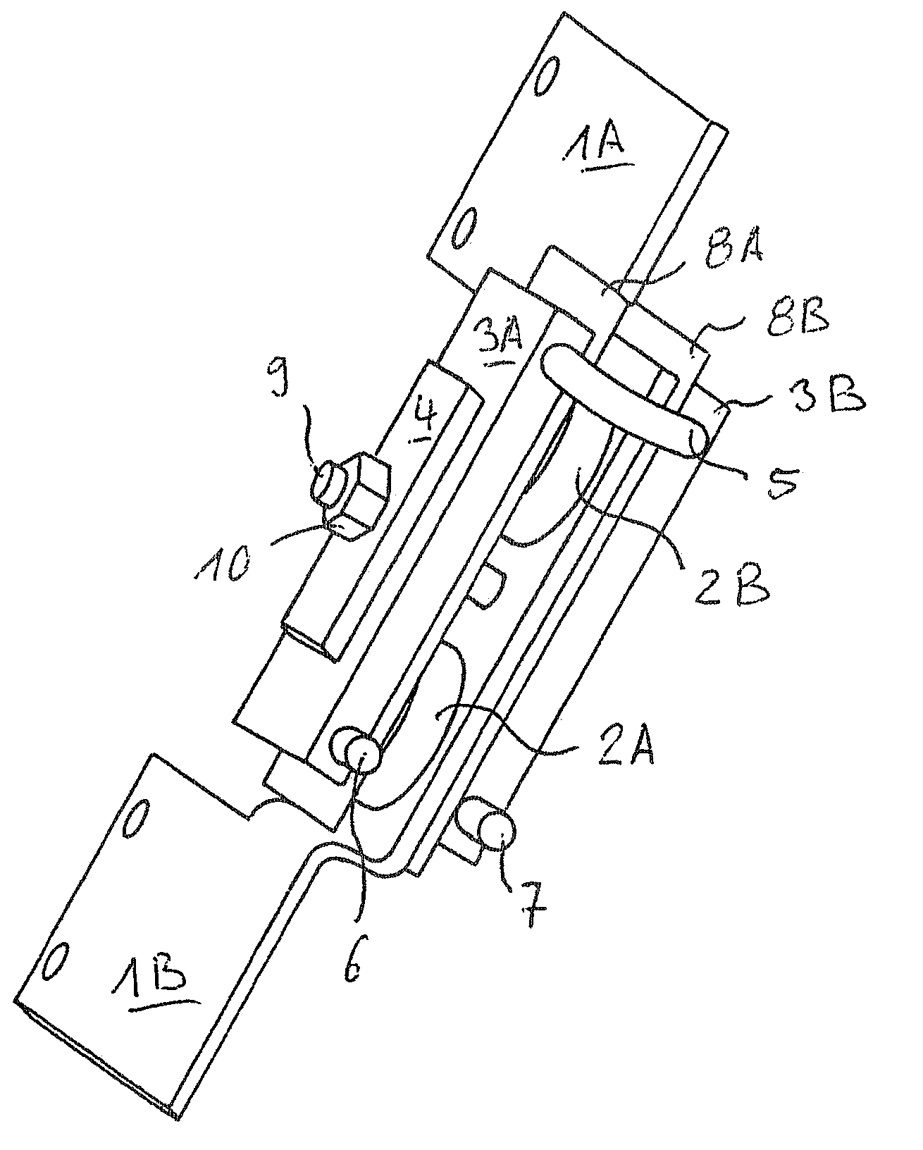
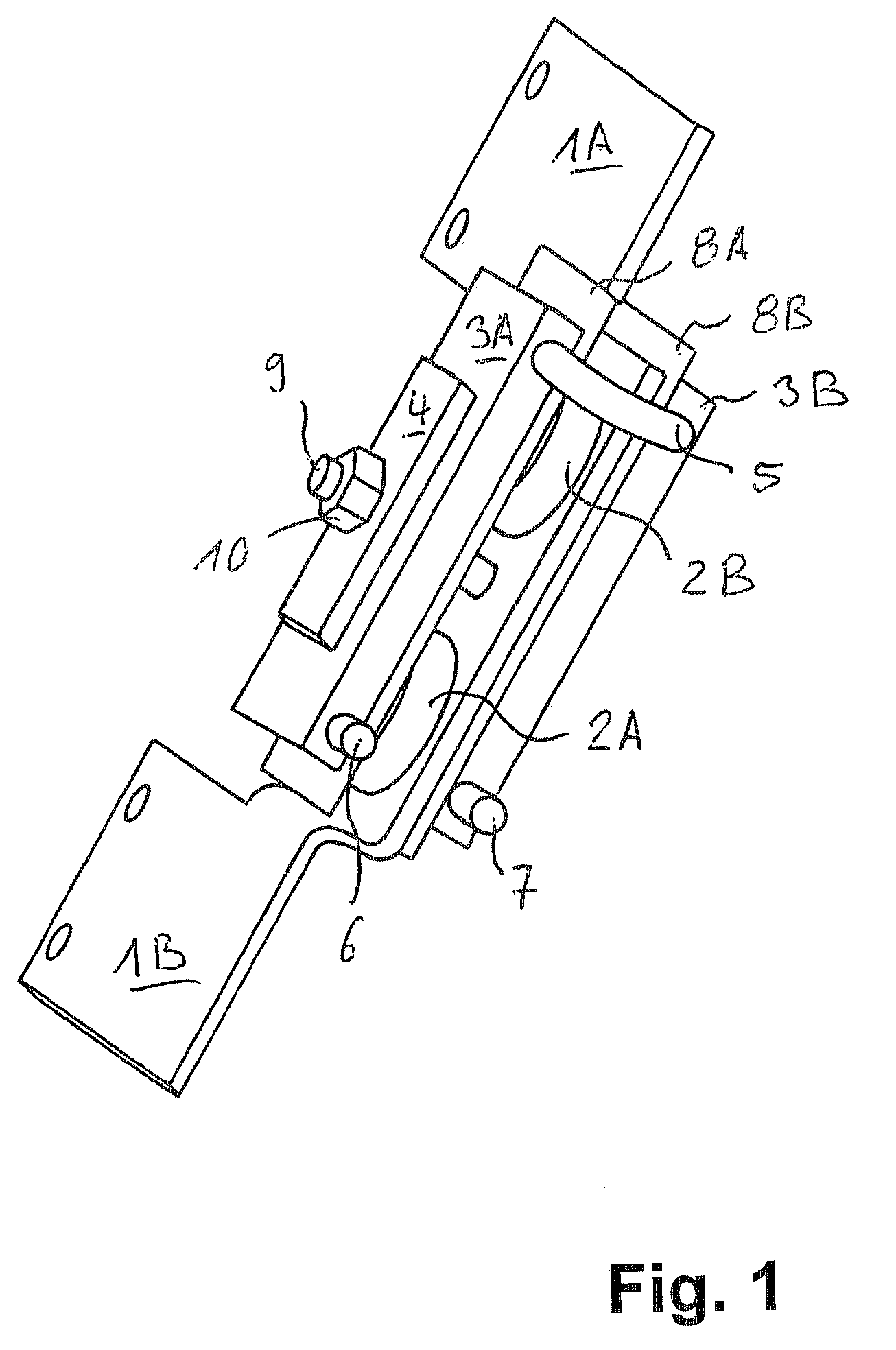
[0029]FIG. 1 shows a perspective view of the switching module, with two thyristor cells 2A and 2B, two cooling bodies 3A and 3B, two current supply means or current-carrying rails 1A and 1B, two insulation means in the form of insulating, reinforced foils (glass-fiber-reinforced silicone foil or foils 8A, 8B having the trademark “Kapton”), and a tension spring 4 (the second tension spring is not shown), and a threaded rod 9 with a nut 10 (the second nut is not shown). The thyristor cells 2A, 2B are disposed centrally and are placed between the current-carrying rails 1A, 1B in such a way that by means of their terminals they rest with their full area on the rails 1A, 1B. On either side of the rails 1A, 1B is a respective glass-fiber-reinforced silicone foil 8A, 8B, disposed such that the cooling bodies 3A and 3B rests with a full area on this foil and is electrically insulated from the respective rail 1A and 1B. Extending through the entire arrangement is a bore or tubular conduit th...


PUM

PropertyMeasurementUnit
electrically conductiveaaaaaaaaaa
electrically insulatingaaaaaaaaaa
thermally conducting propertiesaaaaaaaaaa

Abstract

The invention provides a compact and economical welding control system having an integrated power section. To this end, a switching module is provided for the power section of a welding control system. The switching module has a switching device, at least one cooling body, a current supply and an insulating element which provides a potential-free coolant arrangement. The invention is advantageous in that the potential-free coolant arrangement allows the coolant bodies to be shortened so that less space is required inside the control system and the control system can therefore have a more compact structure. The invention enables even the requirements in terms of the coolant bodies to be reduced, allowing the use of cost-effective cooling tubes or even cooling pipes that are directly connected to the cooling body.

Description

CROSS-REFERENCE TO RELATED APPLICATION[0001]This application is a 35 USC 371 application of PCT / EP2008 / 006904 filed on Aug. 22, 2008.BACKGROUND OF THE INVENTION[0002]1. Field of the Invention[0003]The invention relates to a switching module for the power section of a welding control system, and to a method for producing such a module.[0004]In the course of development of welding control systems, increasingly high packing densities of the power electronics components are demanded, so as to keep the structural size of the tool or the like as small as possible. These higher and higher packing densities require active dissipation of lost power. For that purpose, the components are typically screwed in heat-locking fashion onto extruded hollow profile sections, through which a fluid passes, such as coolant carried in a coolant loop. Aluminum is especially suitable for the extruded hollow profile sections because of its properties, in particular its very good thermal conduction and its ve...

Claims


Application Information

Patent Timeline
Patent Type & Authority Patents(United States)
IPC IPC(8): B23K9/10
CPCB23K9/323
Inventor SCHAEFER, GUENTERSCHOLZ, REINHARD
Owner ROBERT BOSCH GMBH
Why Eureka
Try Eureka